Assembly Creation from 3D Fragments. "Bottom-Up" Design


Assembly Creation from 3D Fragments. "Bottom-Up" Design |
|
3D fragment management
The command for inserting a 3D fragment is "3F:Insert 3D Fragment". The command is called as:
Icon |
Ribbon |
|---|---|
|
Assembly → Assembly → 3D Fragment |
Keyboard |
Textual Menu |
<3F> |
Operation > Insert 3D Fragment |
To insert a 3D fragment into an assembly, you need to do the following steps:
●Select 3D fragment.
The selection is done by one of the following ways:
- insert a new 3D fragment by selecting a file;
- select an already inserted 2D fragment and use its three-dimensional model.
- if the symbol of the model file is dragged from the Windows Explorer or from the service window of the T-FLEX CAD libraries to the 3D window, the 3D fragment insertion command will be started automatically and the given file will be selected for insertion.
· Select or Create Source LCS for the fragment. Selection can be done automatically if the 3D fragment has exactly one or a specially designated LCS.
· Select or create target coordinate system in the assembly.
●Define the values of the fragment external parameters.
This step is skipped when using an existing 2D fragment or if the 3D fragment does not have external variables.
The values of the variables can be set automatically upon attaching 3D fragment to the connector of another 3D fragment.
· Define fragment parameters (optional).
· Finish input.
3D fragment selection
3D fragment can be selected with the help of the option:
![]() <F> Select File.
<F> Select File.
The fragment is selected using the standard File Open dialog. The fragment file can be selected either from a folder on the disk or from a library.
In the transparent mode the following option is available:
![]() <A> Select 2D Fragment.
<A> Select 2D Fragment.
At this moment it is enough to select existing 3D fragment or a file from a library opened in the “Library Explorer”, and the system chooses an indicated element for insertion as the new 3D fragment. Upon selection of an existing 2D fragment in a 2D window the system will use its three-dimensional model.
After insertion of a 3D fragment, the path to its file will be stored in the operation properties. The path can be complete relative to the file of the assembly or relative to the library being used.
In some cases, the system may automatically record the relative path to a reference with respect to the assembly file. Detailed information on the format of the relative links (references) can be found in the chapter "2D Fragments".
External variable value definition
Upon selecting the file, the properties window is filled with parameters of the 3D fragment. One of its groups deals with external variables. The external variables can be displayed as a list – just as in the variable editor. If a custom dialog was created for managing external variables, it will be automatically built in the 3D fragment properties window. If necessary, you can switch between the two modes of displaying the external variables. This is done by toggling the flag "List of Variables" in the properties window.
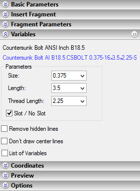
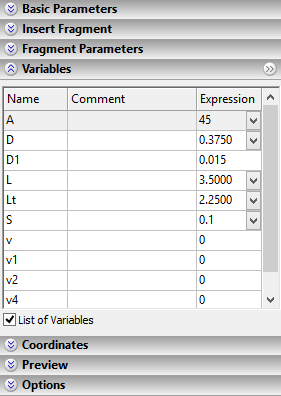
The information about external variables is displayed as long as the 3D fragment creation command is active. You can modify at any time the values copied from the fragment file. To update the 3D window for the changes in the properties window, use the provided button ![]() .
.
If you find it inconvenient to modify the values of the external variables in the property window (as, for instance, because of the large size of the custom dialog), you can put the group of variables into a separate window and enter changes there. Calling the separate window is done by using a special button ![]() at the upper right corner of the group.
at the upper right corner of the group.
If the 3D fragment model does not have any external variables, then, upon executing the 3D fragment insertion command, no tools are displayed for managing external variables.
When a 3D fragment is attached to a connector, the values of the fragment variables can be assigned automatically. (See section «Using 3D connectors».)
Parametric relation definition
Defining relations between parts is the main task for designing parametric assemblies. It demands from the engineer understanding of the T-FLEX CAD tools for maintaining such relations. The first tool that you need to master is the variable editor. The variable editor itself or similar environment is used by the system in multiple occasions, as, for instance, when defining the values of the fragment external variables. Working with the editor, variables, functions and such is described in the chapter "Variables".
Here, let's review a simple showcase for relating part parameters in order to control them from the assembly model. Here we will skip the description of the steps that are not related to the parametric assembly creation (the description of creating part files, attachment, etc.).
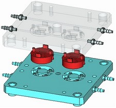
Consider the task – to create a switchboard that includes the mounting plate and a set of switches. The switches can be of two types. The types of the switches differ in some dimensions, however, can be composed from the same parametric parts. The switch lever must snap to two positions "On/Off". The switch itself is made of the following separate parts - the body, the pin and the lever. These parts are parametric, as they rely on the necessary external variables. By using those we can create a parametric model of the switch, whose external parameters define the switch type and the lever position. We need to create a switchboard assembly by using this parametric model of the switch.
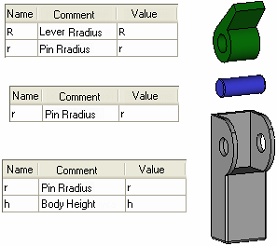
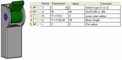
The left-hand side diagram shows the parts of the switch. Tables to the left of each part contain the respective external variables. Originally, the tables appeared in the respective dialogs defining external variables for each 3D fragment being inserted. You can see that the respective assembly variables were entered as the values of the fragment external parameters (which is the switch file at this step). The diagram in the right-hand side shows the switch assembly and the table as appears in the variable editor. You can see on the diagram how the switch parameters are managed: the variables <R> and <h> change depending on the variable <T> value that defines the switch type. The former two define geometrical characteristics of the contributing parts. The variable <a> is responsible for the lever position and defines the model property "On/Off". The external variable <r> will relay the pin radius value to the next assembly.
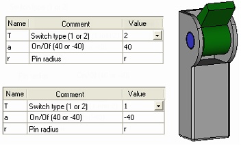
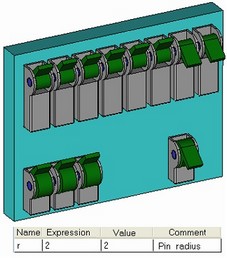
The next step is building the assembly (the switchboard) from the created parametric model of the switch. The left-hand side diagram shows the model of the switch and the two tables of its external variables with different values assigned when composing the assemblies. You can see from the diagram, that the variables <T> and <a> are assigned numerical values, while the variable <r> is related, instead of a value, to the variable <r> of the assembly. This is how the parametric assembly is built. The variable editor of the switchboard provides control over the value of the switch pin radius. Other switch parameters are left fixed. To modify those in the future, you could call the command for editing 3D fragment variables.
When connectors are used, parametric relations between two parts can be established directly, skipping the step of creating the common variable in the assembly. At the same time, the variables of the new part, attached to the connector of another part already inserted into the assembly, will depend only on the values of the first part's variables (see “Using 3D connectors”).
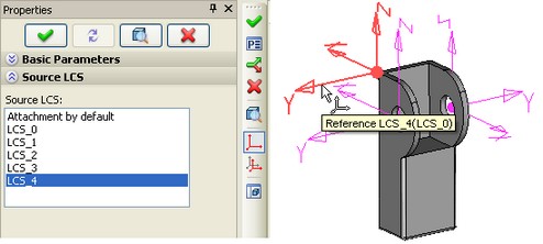
Selection/creation of the source coordinate system
The automatic sequence of the system steps for attaching a 3D fragment depends on whether predefined local coordinate systems existed in the 3D fragment model, and, if so, how many:
●If there is exactly one LCS in the 3D fragment model, and its properties state that it can be used for attaching the 3D fragment, it will be automatically selected by the system as the source coordinates. The system will then proceed to the next step - defining the target coordinate system. If there are more than one LCS in the 3D fragment document, but only one of them is specifically designated as the source coordinates, the system behavior will be the same. (Refer to the topic "Preparing document for use as a 3D fragment" for details.)
●If a 3D fragment model contains several LCS all suitable for fixing the 3D fragment, then T-FLEX CAD picks up the default fixing (by the global coordinate system) and proceeds to defining the target coordinate system. To select a coordinate system, you need to switch to the special mode of selecting/creating the source coordinate system.
●If no local coordinate systems exist in the 3D fragment model, then T-FLEX CAD picks the default fixing (by the global coordinate system) and proceeds to defining the target coordinate system. To create a new source coordinate system, you need to switch to the special mode of selecting/creating the source coordinate system.
Mode of selecting/creating source coordinate system is operated in a separate 3D window, in which the 3D fragment model is loaded. This 3D window is launched forced from the 3D fragment creation command by the option:
![]() <S> Select or Create Source LCS
<S> Select or Create Source LCS
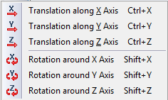
After opening the new window, in addition to standard options, the following options can be initially found in the automenu:
|
<1> |
Select 3D node or vertex as LCS origin |
|
<2> |
Select point to Define Direction of X-axis |
|
<3> |
Select point to Define Direction of Y-axis |
|
<C> |
Reset target LCS |
|
<A> |
Rotate LCS around X-axis by 90° |
|
<O> |
Rotate LCS around Y-axis by 90° |
|
<Z> |
Rotate LCS around Z-axis by 90° |
|
<9> |
Change LCS axes orientation |
When the ![]() option is selected the user is returned to the assembly and the mode of the target LCS specification is enabled. The
option is selected the user is returned to the assembly and the mode of the target LCS specification is enabled. The ![]() option is used for transitioning to the actions related to specification of adaptive fragment’s geometric parameters (more detailed description can be found in the «Adaptive 3D fragments» chapter).
option is used for transitioning to the actions related to specification of adaptive fragment’s geometric parameters (more detailed description can be found in the «Adaptive 3D fragments» chapter).
When working with the option ![]() , selection of the existing LCS is carried out in the 3D window or from the list in the properties window.
, selection of the existing LCS is carried out in the 3D window or from the list in the properties window.
The system allows creating a new LCS based on the 3D fragment's geometry.To activate the mode of creating new source LCS, the first element for determining the origin of the coordinate system has to be selected in a 3D model. At the same time, it is possible to select any appropriate elements of the model in accordance with the active filters of the selector on the system toolbar. After choosing the origin of the new source LCS, the remaining options for defining LCS will appear in the automenu. Creation of the coordinate system is carried out by the same principles as in the specialized command for creating LCS “3O: Construct coordinate system”. Similar options and tools are used in both cases. The center and direction of the LCS axes are prescribed. In addition, the options for cyclical rotation and rotation of axes by 90 degrees are available. In this chapter we will omit detailed description of the LCS creation process.
When creating a new LCS, keep in mind that it is not created in the 3D fragment file. Rather, it belongs to the current "3D fragment" operation and is stored in the assembly document. The created source coordinate system cannot be displayed in the assembly. To modify it, you need to call the 3D fragment editing command and enter the mode of selecting/creating the source LCS.
When the new source LCS is being created, the new line «Fixing by Fragment» will appear in the Source LCS list for the fragment. Also, in the fragment properties window there is going to be a temporary section «Coordinate System Parameters» which enables to control objects selection during LCS creation.
To exit the mode of selecting/creating the source LCS, use the button ![]() .
.
Selection/creation of the target coordinate system
The mode of selecting or creating the target coordinate system is turned on by the automenu option:
![]() <2> Select or create target LCS
<2> Select or create target LCS
In most cases this option is activated automatically after choosing the fragment file and after exiting the mode of creating the source LCS. If a suitable LCS is found in the assembly model then the user actions amount to selecting the LCS in the assembly, to which the fragment source coordinate system should be snapped. If no LCS is selected in the assembly, then the assembly world coordinates will be used as the target coordinate system.
One can also create a new target coordinate system based on 3D model elements. The target coordinate system is constructed using the same tools as those for constructing the source one. The main difference is in that the all actions are performed in the main 3D window for the current assembly. The 3D fragment model is positioned in the space according to the properties of the target coordinate system being defined.
The options for defining elements of the new target coordinate system appear after selecting the origin point of the LCS. Upon selecting the origin, you can proceed with orienting X and Y axes.
In case you couldn't orient the LCS as desired from the beginning, you can use the tools for coordinate system redefinition. Those allow quickly rotating an existing LCS around its axes by 90 degrees ((![]() ,
,![]() ,
,![]() ), cyclically reassign the axes of the coordinate system with the fixed origin (pressing
), cyclically reassign the axes of the coordinate system with the fixed origin (pressing ![]() switches the axes assignment).
switches the axes assignment).
|
|
|
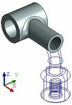
Fragment position in absolute coordinates |
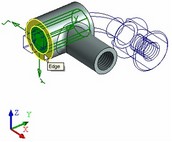
Fragment position after selecting an edge for target LCS |
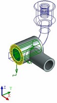
Fragment position after using the tool of rotating X-axis by 90°. |
To reset all data currently used for defining the target coordinate system, use the automenu option:
![]() <C> Reset target LCS
<C> Reset target LCS
Choosing 3D connectors
3D connector can be chosen in the mode of selecting or creating target coordinate system activated automatically right after entering the fragment insertion command (option ![]() ). In this mode it is necessary to make sure that the selector's filter for choosing connectors
). In this mode it is necessary to make sure that the selector's filter for choosing connectors ![]() is activated on the system toolbar.
is activated on the system toolbar.
For searching connector on some part, bring the cursor to one of the elements associated with the connector. In standard elements, for example, in bolts, the screw-threaded faces of the bolt shaft can be chosen as an associated element. Already upon bringing the cursor to such element, the connector is highlighted. Press ![]() for choosing connector.
for choosing connector.
Assigning additional transformations
Controlling additional transformations is carried out with the help of a dragger in the 3D window and group «Transformations» of the properties window and the «Transformations Groups» dialog of the «Main transformations» section of the properties window. The dragger is always present upon insertion of a 3D fragment, if the option «Use Draggers» is turned on in the properties window.
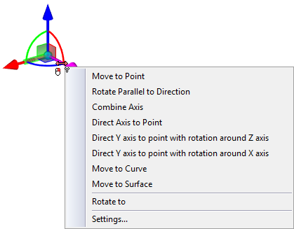
The dragger enables to define an unlimited number of translational transformations along the indicated axes in-plane shifts or rotations of selected axes by a required angle in the required plane. The dragger represents itself an image of the coordinate system. The coordinate axes are connected to each other by color arcs; adjacent planes are connected with each other via conditional small color squares, the dragger center is marked by a grey ball. Different parts of the dragger are the active elements intended for defining certain transformations: |
|
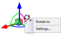
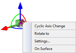
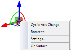
●the dragger axes are intended for defining translations; ●the dragger arcs are used for defining rotations; ●the images of coordinate planes are used for translation in the planes XY, XZ, YZ; ●the dragger center is used to manually enter the mode of dynamic snapping. Upon bringing the cursor to different active parts of the dragger the cursor changes its appearance prompting to set the corresponding types of the additional transformations. Next to cursor there is going to be a tooltip providing information about the type of offered transformation. The selected element of the dragger is highlighted with a different color. When a user points at the axis he can move to setting the translation along the chosen axis. Upon pointing at the arc, the system prompts to set rotation in the corresponding plane. At the same time, the closest to the cursor axis of the dragger is also selected so that a user could define a rotation by directing the selected axis towards a specific element of the model. When specifying the coordinate plane’s image the user can start defining the shift across the selected plane. When selecting one of the dragger’s elements mentioned above the following commands become available in the context menu: ●- for translation along the axis; ●- for translation in the plane; ●- for rotation about three axes; ●- for translation along three axes. |
|
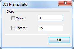
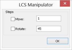
The Settings option of the menu defines the step in the change of the distance and angle upon translations and rotations of the dragger.
For defining transformation with the help of the dragger a user has to choose an active element of the dragger by pressing ![]() . Then, without releasing the mouse button a user can move the cursor. The transformation will have been set upon releasing the mouse button.
. Then, without releasing the mouse button a user can move the cursor. The transformation will have been set upon releasing the mouse button.
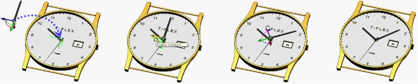
Begin with inserting a fragment (the minutes arm) by selecting the edge on the arm pin to define the target LCS (of the arm fragment position) |
Turn the arm. To do this, select the desired element of the dragger and depress the left mouse button |
Drag the mouse whilst holding the mouse button down. Turn the fragment about the axis |
Complete the transformation definition by releasing the mouse button |
Also, after dragger's selection it is possible to release the mouse button, shift the cursor and choose a new element (indicate a new point in space) for fixing transformation by pressing ![]() twice.
twice.
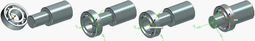
Start inserting the fragment (the bearing) |
Select the round edge to define the target coordinate system (the fragment's position) |
Click to select the dragger's axis to define the translation along the axis |
Select the round edge to define the final point of the translation |
Click at dragger center signifies transition to operations for modifying the target coordinate system. Simultaneously, the mode of dynamic snapping gets activated. In this mode, the fragment image is attached to the cursor. Upon bringing the cursor to the elements of the model, the fragment image will be immediately put in a position showing the location of the fragment in case the element is selected. In this mode it is possible to click at the free spot in space or choose an element of the model for attaching. In the first case, new additional transformations for placing the fragment at the spot of a click are created. After choosing the new element of the model for attaching, all previously defined transformations may be deleted.
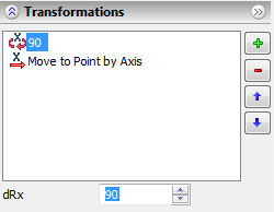
Group «Transformations» in the properties window can be used for controlling, correcting numerical values, creating or deleting transformations of a 3D fragment. In the special field the list of all additional transformations, defined at the moment for a 3D fragment, is shown. Each transformation is marked by a special symbol, denoting its type (translation or rotation about some axis). If the value of the transformation is set via a constant, then this value is shown next to the symbol. If the transformation was attached to the element of the model, then the name of the element is indicated next to the symbol. The elements of the list are shown in the order in which there were created. Several successive transformations of similar type are automatically summed up. |
|
Below the main list of transformations there is a field for entering and editing the values.
To the right of the transformation list there are graphics buttons. The button |
|
Upon pressing the button |
|
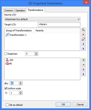
The user has also a capability of creating individual transformations groups for 3D fragments. Classifying transformations into groups allows the user to create simultaneously several variants for the 3D fragment locations in the assembly.
For example, let us suppose there is a variant of the room’s 3D layout. It is required that the fragment (barrel) change its location depending on the location of walls and addition of new objects to the layout.
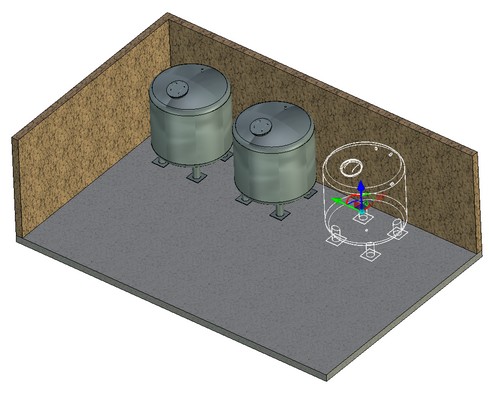
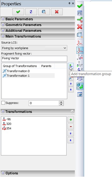
To do so, in the properties window of the 3D fragment (barrel) in the «Main Transformations» section we find the «Transformations Groups» dialog. With the help of the ![]() button we add the transformations group, namely we specify the values for translations along the X and Y axes and rotation around the Z-axis.
button we add the transformations group, namely we specify the values for translations along the X and Y axes and rotation around the Z-axis.
It is important to remember that by default all transformations for a 3D fragment are created in a single transformations group.
Each transformations group has it name. The elements of the list are shown in the order that correspond to their creation.
To control visibility of various locations of the fragment there is the «Suppress» flag. Next to the flag there is a field where the numbers can be entered or the numeric variables can be written down. If the value different from zero is entered into the field, the transformations group becomes suppressed. To make the work in the assembly more convenient let us specify the visibility of the fragment’s locations with the help of the variable.
After specifying several positions of the fragment (barrel) with the help of the transformations group we obtained the capability of manipulation of its translation in the easiest and fastest way.
In this case for displaying the changes in the transformations in the 3D window it is required to use the 3D model update button ![]() .
.
The graphics buttons are located to the right of the list of transformations group.
The ![]() button allows us to add a new group to the transformations group.
button allows us to add a new group to the transformations group.
When pressing the ![]() button the last group of transformations in the list is removed.
button the last group of transformations in the list is removed.
The ![]() button allows us to remove all transformations groups.
button allows us to remove all transformations groups.
When pressing the ![]()
![]() buttons the order of execution of transformations groups changes.
buttons the order of execution of transformations groups changes.
Upon attaching a fragment to the connector, the system can automatically move to defining additional transformation, if the corresponding instructions are set in the connector (see chapter «Local Coordinate Systems»).
After insertion 3D fragment all prescribed additional transformations are recorded in the common transformations list of the 3D fragment. A separate record is generated for each additional transformation in the transformations list of the 3D fragment.
Fragment updating
![]() Update 3D fragment automatically in case of changed parameters. If option is set, a fragment will be automatically updated when its variables or adaptive parameters are changed.
Update 3D fragment automatically in case of changed parameters. If option is set, a fragment will be automatically updated when its variables or adaptive parameters are changed.
Also you can update fragment manually by pressing update button in the upper part of the Properties window.
Working with 3D model structure
In the course of working with an assembly, you may need to access auxiliary information about the state of 3D fragments. This can be querying their position in the assembly tree, reviewing existing errors, etc. Various tools are provided for this purpose. We will review those tools within the current topic.
3D fragments and Parts are displayed in the "3D model" window. This window shows the complete hierarchy of the assembly model. It allows finding the place of each 3D fragment in the model structure among other 3D operations and construction elements. 3D fragments can be displayed at the root of the model structure, along with Bodies and Arrays. If a 3D fragment is an assembly itself, containing nested 3D fragments, the structure of all its nested elements is reflected in the general 3D model tree as well. For nested fragments of any level the commands of editing external variables and creation of detail drawing are available in the context menu.
To ensure the full support of handling the nested 3D fragments, you need to bring into the editing environment the subassembly that hosts the fragment of interest.
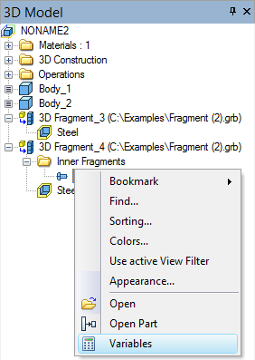
In the window «3D Model» for 3D fragments, besides the name of the file and the operation, various additional information can be shown, if needed, – file path, identifier, memory size allocated for mesh, memory usage for geometry, recalculation time, the name and notation for specification. The amount of displayed information can be set in the dialog box of the command “Appearance”. This command can be called from the context menu by pressing ![]() in the window «3D model».
in the window «3D model».
If errors are detected in the model, the affected elements are marked in the model tree with the special symbols:
1.If an error was detected within a 3D fragment model or its coordinate systems, a mark is displayed.
2.The 3D fragments, whose files were not found by the specified reference, are marked by a red cross. ![]()
3.The suppressed 3D fragments are marked by a blue cross. ![]()
Detailed information about all errors is displayed in the “Diagnostics” window. Right clicking ![]() over a message brings up the context menu. If the message refers to a 3D fragment of the first level, then you have access to all commands for handling that 3D fragment. If the message reports an error within nested fragments, then the only command for handling the fragment is “Show fragment structure”.
over a message brings up the context menu. If the message refers to a 3D fragment of the first level, then you have access to all commands for handling that 3D fragment. If the message reports an error within nested fragments, then the only command for handling the fragment is “Show fragment structure”.

The fragment, within which the error was identified, is automatically highlighted, showing the branch of the assembly tree that includes the failing fragment. The right pane of the window displays the information about variables used in the fragment: their names, values and comments. To fix the error in the fragment file, you can open the file by pressing the button [Open]. For example, the error in the fragment model can be caused by an invalid variable value. To open the fragment with the current variable values use the button [Detail].
Normally, the assembly tree displays only its contributing 3D fragments. To view the full assembly structure, use the "Assembly Structure" window.
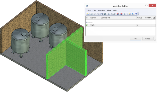
Layout creation
To create a 3D fragment using the layout technique, use the following option in the main automenu of the 3D fragment insertion command:
![]() <G> Create 3D Fragments by Workplane (Layout)
<G> Create 3D Fragments by Workplane (Layout)
Upon calling this option, the mode of selecting 2D fragments is activated, as indicated by the glyph attached to the pointer and the pushed icon in the automenu. Now, you need to select a 2D fragment or a set of 2D fragments to use for creating the 3D layout.
Upon selecting 2D fragments, specify the workplane on which the 3D fragments will be placed. The workplane for the 3D fragment orientation can be defined anew, regardless of the workplane that was hosting the 2D fragment. The workplane selection is done by the option:
![]() <W> Select Workplane to set view direction of projection
<W> Select Workplane to set view direction of projection
The selection can be done either in the 2D or in the 3D window, provided, that the display of the workplane in the 3D window is turned on.
Upon confirming the selection by pressing ![]() , the 3D layout will be displayed in the 3D scene, created based on the 2D fragments.
, the 3D layout will be displayed in the 3D scene, created based on the 2D fragments.
If errors occur when creating a layout, for example, if the vector of the 2D fragment was not associated with the workplane, the system positions the 3D fragment in the absolute coordinates without a possibility for attaching to an LCS until the fixing vector is associated with the workplane in the fragment document. Besides, a warning is displayed, "Can not find associative WorkPlane in Fragment document".
There is a capability of controlling location of the 3D fragment directly in the 3D window domain. To change location of the 3D fragment in the 3D window domain it is required to use the option in the automenu of the 3D fragment insertion command:
|
<L> |
Layout mode |
When the layout mode is enabled only the axes of the workplane are displayed on the dragger. All transformations with 3D will automatically be transferred onto the 2D drawing after pressing ![]() . Transformations with translation of 3D fragments are displayed on 2D only with the layout mode enabled.
. Transformations with translation of 3D fragments are displayed on 2D only with the layout mode enabled.
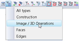
It is also possible to edit location of a 3D fragment when choosing configuration of the selector View /3D operation Elements.
The layout mode is used only for 3D fragments with fixing vector.
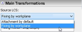
For the 3D fragments for which a 2D fragment has a fixing vector, when choosing the source coordinate system there is an option of fixing by the workplane. Orientation of the source coordinate system of the fragment snapped to the workplane coincides with the orientation of the fixing vector on 2D. |
|
3D fragment parameters
Detailed setting of many parameters for a 3D fragment can be accomplished at any moment in the parameters dialog box. It is called with the help of the option of the command for creating and editing the fragment, and, also, from the context menu by selecting operation:
![]() <P> Set entity parameters
<P> Set entity parameters
The dialog contains three tabs. The tab [General] contains common parameters for all 3D elements.
Most of the parameters on the tab "Operation" are already described in the chapter "Fragments" of the two-dimensional design manual, as those are used when inserting 2D fragments. Exception is the following two parameters.
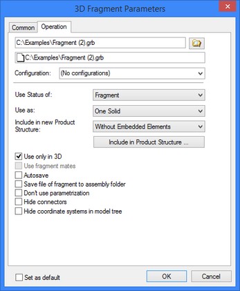
Configurations can be used for defining the values of the external variables in 3D fragments. For this purpose, the properties window provides a control for selecting the current configuration. The user can select any existing configuration, or the setting "(No configuration)".
Use as. This parameter can take one of the two values: "One Solid" or "Separate Solids". With the value "Separate Solids" used, the additional operation "Divide Solid" is applied for dividing the fragment into the separate bodies. This is necessary in the cases when the 3D fragment itself is made of several bodies, while just one of them should be used, for instance, in a Boolean operation with another assembly element. It will be impossible to select a particular body of the 3D fragment without dividing into separate bodies. Instead, you will be always getting the whole operation "3D Fragment" selected as one object. The operation "Divide Solid" can also be done manually after inserting the 3D fragment, with the same result.
Use only in 3D. This flag allows turning off the display of the two-dimensional representation of the fragment in the 2D view window.
Use Fragment Mates. When a different assembly unit, in which the mates have been created and the degrees of freedom have already been defined, is inserted into the assembly, there is a possibility to transfer the entire mechanism into the new assembly by using only operation of insertion of a 3D fragment. To insert such fragment-mechanism into the assembly, the option of using the fragment «As Separated Bodies» and the option «Use Fragment Mates» have to be turned on simultaneously.
Autosave. When changing the values of external variables of the fragment in the assembly the fragment’s file is resaved according to the new values. The fragment’s file is updated at the moment of saving the assembly file. This flag can be conveniently used for obtaining detail drawings. If projections are used in the file of the fragment, then for their recalculation during autosaving the mode of automatic update must be selected in the projection’s properties.
Copy together with assembly. If this flag is enabled, then next to the assembly file the folder is created, which has the name of the assembly file, and the fragment’s file is saved into the folder. The relative path for the fragment is created.
Do not use parametrization. When this flag is enabled, external variables of the fragment cannot be changed. The “Variables” window is not invoked from the context menu of the fragment and does not appear during the fragment editing.
Hide connectors. When this flag is enabled connectors of the fragment are not shown in 3D scene and in the tree of a 3D model.
Do not show coordinate systems in the tree of a model. When this flag is enabled external coordinate systems of the fragment are displayed in 3D scene, but are not shown in the tree of a 3D model.
Via the tab [Transformations], it is possible to work with list of all geometric transformations which have been applied to the given operation of a 3D fragment. Among those, there could be:
●additional transformations defined upon creating or editing 3D fragment;
●transformations, assigned in the command “3EG: Transform Element”;
●transformations for the «Exploded View» mode;
●specific service transformations for performing the functions of attaching a 3D fragment.
Any transformation can be applied either permanently or only in the special mode of exploded view for the assembly. This is controlled by the corresponding flag in the settings of each transformation.
3D fragments and Parts can be subject to a special type of a transformation called “Attachment…”. Instead of somehow transforming the body of a 3D fragment in the space, this type of transformation merely defines the attachment by the coordinate systems. This transformation is introduced automatically by the system upon inserting each 3D fragment. Its name depends on the attachment type of the 3D fragment:
●“Fix by Fragment LCS” - is the 3D fragment attachment transformation in which the fragment LCS was used as the source coordinates.
●“Fix by Assembly LCS” - is the 3D fragment attachment transformation in which the source coordinate system was created on the fly in the transparent mode when inserting the 3D fragment.
●“Fix by Workplane” - is the 3D fragment attachment transformation in which the attachment is defined by the 2D fragment (layout).
When suppressing the transformation defining a 3D fragment attachment, the fragment model is positioned in the scene by snapping the 3D fragment world coordinate system to the assembly world coordinates.
To disable any transformation, set the flag “Suppress” in its properties. The input box next to the flag check box allows entering numerical values or non-textual variables. The transformation is considered suppressed whenever the entered expression is not equal 0.
3D fragments possess another special type of transformation, providing for the automatic 3D fragment exploding data copying from the properties of its source coordinate system. The respective chapter about local coordinates reads: if you plan to use a given LCS as the source coordinates for attaching a 3D fragment, then you can define, among its properties, the necessary translation/rotation for future exploding. This transformation is called “Source LCS Transformation”. It only becomes available, when the source LCS of the 3D fragment actually has those properties defined. Such transformation cannot be modified in any way.
If the exploding transformation was not defined for the source coordinate system, then the system may try to automatically assign some transformations at the time of the 3D fragment creation. The numerical values of the offsets will be automatically calculated based on the overall dimensions of the 3D fragment model. A new transformation named “Transformation_<No.>” will be added to the list of existing transformations at this time. This transformation will have the flag “Only for exploded view” set. You can turn off the system’s automatic appending of the exploding transformations upon 3D fragment creation. The setting is accessible in the system options on the tab “3D” (the command “Customize|Options…”, the parameter "Explode assembly (3D Fragments) automatically").
A special flag “Apply exploded view transformation of base elements” allows exploding a given 3D fragment with respect to its fixing point, accounting for exploding transformation of the base elements. That means, turning on the flag additionally moves the fixing point of this 3D fragment per the transformation of the base element.
Creating Boolean operation based on 3D fragment
Just like other operations, 3D fragments can be used in Boolean operations. For example, you can subtract the body of a 3D fragment from another part. If necessary, you can define a property in the 3D fragment document, that will specify what type of the Boolean operation will be automatically performed upon inserting this document into an assembly (see the section "Preparing a T-FLEX CAD document for use as a 3D fragment"). If such property is defined, then, upon inserting the 3D fragment, you need to select one of the bodies in the assembly. If the assembly consists of a single body, it is selected automatically. This body will be used as the target body in the Boolean operation. The tool body will be one of the bodies of the 3D fragment, or the fragment altogether, depending on the property setting.
The option can be useful, for example, when inserting holes into the body of a part, or in mold design, when subtracting the part body from the block yields the stamp or master form.
The following options are used for selecting the target body of the Boolean and for undoing the selection:
![]() <B> Select solid to create Boolean.
<B> Select solid to create Boolean.
![]() <D> Cancel selection of solid for Boolean creation.
<D> Cancel selection of solid for Boolean creation.
Reference update
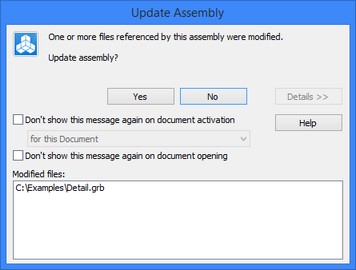
Let us explain the use of the option "Update fragment data".
When inserting a 3D fragment, the system internally creates a copy of the fragment three-dimensional model in the assembly drawing. Upon a new regeneration of the assembly, the system no longer loads the 3D fragment geometry data; rather, it uses the saved data. To maintain the assembly up to date, the system constantly tracks the file. The latter changes if the fragment file was edited and saved. If files changed, the system instantly offers updating the references to the documents, that is, loading new geometry data of the modified 3D fragments.
Pressing the button [Yes] refreshes the data of all modified fragments. If the assembly contains a significant number of fragments, the updating procedure may take significant time, even though only one fragment actually required update. Therefore, you can press the button [No] instead, and then select a specific fragment and refresh only its respective data.
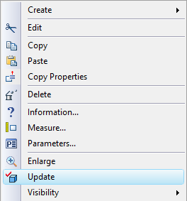
Local update of a selected 3D fragment is possible with the command "Update" of the context menu coming up upon right clicking ![]() over the 3D fragment operation.
over the 3D fragment operation.
Updating of all modified fragments can be forced by the command File|Fragment|Refresh Files. However, if some of the 3D fragment files were not modified, then the 3D fragments are regenerated neither upon the full regeneration nor upon refreshing the 3D fragment references. To guarantee the regeneration of the full assembly with all its member 3D fragments, use the file converter with the parameter set, "Don't Check Documents Versions (Resave All)". The detailed information on working with the converter is provided in the chapter "Converting documents created in earlier versions of T-FLEX CAD".
Preparing a T-FLEX CAD document for use as a 3D fragment
Any T-FLEX CAD document can be customized to simplify in certain circumstances its usage in assemblies as a 3D fragment.
Customizing document status
3D fragment tab in ST: Set Model Parameters command provides possibility to specify default LCS used for fragment fixing, specify type of insertion, set parameters for automatic Boolean operation.

Automatically create Boolean Operation
When inserting a 3D fragment, one can automatically create a Boolean operation of a specified type. The target body will be the selected body in the assembly, while the tool body - one of the bodies of the 3D fragment, or all fragment bodies at once.
Setting up automatic creation of Boolean operation is performed with the help of several parameters:
Operation Type. This parameter defines the type of the Boolean operation (addition, subtraction, intersection) that will be created upon inserting the fragment in the assembly. The type can be selected from the list.
Create operation with:
Use the whole Model. With this option checked, the whole 3D model of the fragment will be used as the target body of the Boolean operation.
Use single operation. Selecting this option makes the Boolean use just a single operation within the fragment. The desired operation can be selected from the list of all existing operations.
In the case when a body is used in the Boolean, that is not visible when working with the document of the 3D fragment, it is possible to place it in a special layer marked as “Visible only when model is used as a Fragment”.
Let’s review an example of automatic creation of a Boolean operation on inserting a fragment. Suppose, there is a 3D model of a building wall, and we need to insert a window in it as a fragment. To do so, let’s create the window model in a special way. Create a tool block as a dummy for cutting the opening in the wall for inserting the window. Then call the “Insertion of 3D Model as Fragment” dialog box (see above). Set the operation type – Subtraction, Use single operation. From the list of operations select the one that created the tool block.


3D Fragment
Fragment name. This parameter defines the name with which the fragment will be displayed in the assembly’s model tree.
Folder Name. This parameter specifies the name of the folder into which the fragment will be placed in the assembly’s model tree.
Fragment’s name and folder’s name are read from the fragment’s file only upon creation of the new fragment. If the values of these parameters are changed, then upon update of the fragment in the assembly the name and the folder will remain the same.
Insertion method. From the drop-down list one of the options can be selected:
●Standard. Upon insertion into the assembly the translation of the fragment is possible only with the help of the manipulator of LCS (dynamic translation is disabled);
●Fastener. When inserted into the assembly the fragment dynamically moves after the cursor of the mouse;
●3D arrangement. This method of insertion is used for quick creation of the arrangement in 3D scene. In the fragment’s file special attachments to the floor, walls, ceiling, horizontal surfaces must be created. These attachments are defined by means of connectors with the specific parameters;
●By points. A fragment can be fixed to the selected in the 3D scene points upon insertion. Its size changes according to the distance between the points.
●Smart fragment (macro). This method of insertion is used for parametric fragments whose insertion scenario is described in the program (macro) stored directly in the file of the given fragment or in the external module (DLL). When inserting the file as a fragment the user-specified macro will be executed.
“Default LCS used for Fragment fixing” is selected from the list. The list contains all local coordinate systems of the model that have the flag “Use for Fragment insertion” set. When inserting such document as a 3D fragment, the thus defined coordinate system will be automatically offered as the source LCS.
If necessary, the permitted degrees of freedom can be set in the properties of the prepared coordinate system, which will insure the correct behavior of the given 3D fragment in an assembly in the mode of moving mated elements (see the chapter “Mates and degrees of freedom”).
For uncomplicated parts, which can be conveniently inserted into the assembly in the mode of dynamic snapping, the given mode can be turned by default.
Insert 3D fragment on layer. This parameter defines the name of the layer onto which the fragment will be placed upon its insertion into the assembly. If in the fragment’s document the “Insert on layer” parameter is enabled, but upon insertion of the fragment into the assembly this layer does not yet exist, then this layer is created automatically upon request.
Don’t show the message “Fragment doesn’t have bodies”. By default this parameter is disabled. In this case the system does not allow for insertion, into the 3D assembly, of the fragment in which the 3D model is absent or suppressed. The corresponding message in the diagnostics window appears as comments. When this flag is enabled the system allows for insertion of “empty” fragment without issuing any messages.
You can define options for section views on 2D projections on the Sections tab.
For some models (future components of assemblies) it can be helpful to define special settings for preventing their cutting when used in section views of 2D projections. For example it is known that bolts should not be cut on section views of assembly drawings. This option will help to avoid time consuming manual customization of 2D projection parameters for assemblies that contain such parts.
New condition can be created with the help of ![]() button. Section Application Condition section will appear with the lists of conditions and LCS names.
button. Section Application Condition section will appear with the lists of conditions and LCS names.

Conditions are organized in relation to the alleged source fragment LCS that exists in a document of a future 3D fragment. For example a part may remain uncut if a section plane goes through a specified axis of the source LCS, or coincides with one of the main LCS planes.
Assembly variable definition
You can assign an assembly variable counterpart for any external variable of the current document. This can be done in the case, when the external variable drives, for instance, a characteristic parameter (such as, say, diameter), while the assembly variable name has already been defined (for example, D). When assembling this document as a fragment, this assembly variable name will be automatically substituted for the fragment variable in the dialog for defining external variable values (provided that this variable exists in the assembly).
The assembly variable name can be defined in the variable editor. The command is called from the editor textual menu: "Variable|Assembly Variable Name…". Detailed information on working with the variable editor is available in the chapter "Variables".