Top-down Assembly Design


Top-down Assembly Design |
|
Main chapters
Create Assembly Structure in "Assembly Structure" Window
Working in Context of Assembly
Filling an Assembly with Geometry
Two Basic Ways to Create Parts in Assembly
Parts That Do Not Depend on Assembly
Unload Geometry with Possibility of Subsequent Updates
Positioning, Scaling, and Variation of Fragments in Assembly (Fragment Transformations)
Variations of Fragments Relations with Assembly when Designing Top-down
Other chapters
Saving Geometry from Assembly to Separate File
When you use "Top-down" design, you can create parts in an assembly based on the geometry of other parts of the assembly. This is a fundamental difference from "Bottom-up" design, where parts are edited separately, independently of other parts in the assembly. That's why we will see how parts in the assembly will contact with each other only when we have finished editing the part and updating the assembly. In "Top-down" design, an assembly defines the dimensions, position, and contact elements of its parts and subassemblies, which means that top-down design requires top-down communication: the relation between an assembly and assembly fragments. The relation between the assembly and the assembly fragments is performed by the Reference Element. Reference Element borrows geometry from assembly to part. The Reference Element may borrow major elements of the model and topological elements. Control of relations between fragments and their relations with the assembly, the fragments variations, navigation through the assembly are performed in "Assembly Structure" window.
The Top-down design principle and the Reference Element mechanism allow you to solve problems that arise in the development of complex assemblies. For example, the user can borrow the geometry of elements from the elements of higher-level fragments in the assembly structure, or from fragments located in "parallel" subassemblies. The user can receive changes of the uploaded geometry from the source document or update the source document in accordance with the changes in the uploaded file at any time.
Thanks to the Reference Element mechanism, it is possible to work effectively in a team, where each user performs his task. For example, when designing an excavator cab, the cab body parts are developed by one user, and other users do not have access to this file. The geometry of the cabin can be uploaded to a separate document so that several users can work in parallel.
|
|
On the basis of these unloaded elements another user can create equipment in the cabin, having full data on the current dimensions of the cabin. In this case, it is possible to snap to the unloaded geometry and update the unloaded geometry in accordance with the changes in the source file of the cabin. Then the changes made in the cab may be transferred to the general assembly.

|
|
The "Top-down" design method cannot be considered suitable for all assembly design cases. It has a number of limitations:
●a more complex scheme of the organization in comparison with "Bottom-Up" method;
●less resistance to topological changes in the 3D model;
●parts are less convenient when using the same 3D model in different assemblies;
●higher requirements to computer resources.
"Top-down" and "Bottom-up" design methods can be combined. The "Bottom-up" design method is useful when adding standard parts to an assembly, parts with strictly defined geometry. The "Top-down" design method is preferably used in the design of parts and assemblies that provide interconnection and fastening in the assembly of structural elements that have a strictly specified geometry.
Create Assembly Features Using "Top-down» Design
The commands for creating assembly elements.
●<3F> Insert 3D Fragment. Allows you to insert a fragment by LCS. It is used during "Bottom-up" designing.
●<FM> Create 3D Fragment. Allows you to create a fragment in the structure of an existing assembly. It is used during "Top-down" designing.
●Detail. Detail>Create and Detail > Unload. Allows you to create a fragment on the basis of a body in the assembly. Creates a detail file that depends on the body or fragment in the assembly. The command is available in the context menu of the fragment or body.
●<3RE> Reference Element. Allows a fragment to borrow geometry from an assembly or another fragment. Reference elements carry out the relationship on which the principle of "Top-down" design is based. You can only create reference elements in the context of an assembly (except for internal references to resolve recursions – see the "Reference element" subsection).
●Open in Context: The command is available in the context menu of the fragment or body. Edit in Context: the command is available in the Create 3D Fragment command dialog.
●<Alt+7> Assembly Structure. The command opens the "Assembly Structure" window. The window is required to navigate the assembly and control assembly changes.
Various options of these commands, their combination when creating assembly elements, allow you to create assemblies with complex hierarchical relationships. Fragments can depend on both the assembly and other fragments in different ways, you can combine the "Top-down" design principle with the "Bottom-up" design principle. The types of fragments and how they relate to each other and to the assembly are described in the section "Variations of fragments relations with assembly when designing ’Top-down’".
Create Assembly Structure in "Assembly Structure" Window
You can create an assembly structure both during operation and in advance. The recommended way to operate using "Top-down" design is to create a structure of hierarchically related fragments, and then edit them, starting with fragments that are independent of others, moving on to the fragments that will be built on the basis of those that have already been created. It is difficult to fully guess the final structure, so you can create only part of it, and to supplement the structure in the process.
To create a hierarchical assembly structure, you should create an assembly file.

Then you should save the assembly file. Open the Assembly Structure <Alt+7> Assembly Structure window.

Next, in the "Assembly Structure" window, you should call the context menu for the created file.

Select the Create 3D Fragment command. In the appeared dialog, specify the name, and do not enable Edit in Context option, because first you need to create the assembly structure. You can edit the fragments both in context and not in the context of the Assembly later, when the user begins designing. After you finish working with the fragment creation dialog, the fragment file will be saved in the specified folder. By default, the new fragment file will be saved to the folder where the Assembly file is located.

Working with the fragment creation dialog is described in the corresponding section below.
Similarly, by calling Create 3D Fragment command from the context menu, you can create a structure of any complexity for the fragment for which you want to create a nested fragment.

After you have finished creating the structure, you need to save the main Assembly file in which you worked to create the structure. Next, you need to fill the fragments with geometry. This should be done in the context of the Assembly if you want to create Reference Elements.
Working in Context of Assembly
When you edit a fragment in the context of an Assembly, the 3D scene of the fragment is combined with the 3D scene of the Assembly from which the fragment editing in the context was invoked. 3D scenes are combined with the transformations that the fragment received in the Assembly. While operating in the context of an Assembly, we are in a fragment file. All the changes we make only affect the fragment file. The 3D Model window displays the construction elements a fragment file. "Assembly Structure" window shows the structure branch starting from the Assembly in the context of which you are working. Working in the context of an Assembly has two main functions.
●It allows you to understand the position and dimensions of the fragment directly in the Assembly.
●It allows you to create Reference Elements.
The main tool for linking an Assembly to fragments in "Top - down" design is the Reference Element. Reference Elements can be created automatically or manually. More information about the cases in which a reference element is created automatically is written in the "Reference Elements" subsection. You only need to create reference elements manually in the context of an Assembly using <3RE> Reference Elements command.
In order to open a fragment in the context of an Assembly, you need to double click ![]()
![]() on it in "Assembly Structure" window or in the context menu of the fragment to choose the
on it in "Assembly Structure" window or in the context menu of the fragment to choose the ![]() Open in Context command. The context menu of the fragment can be called in the "3D Model" window or in the "Assembly Structure" window.
Open in Context command. The context menu of the fragment can be called in the "3D Model" window or in the "Assembly Structure" window.
The fragment will be opened in the context of the Assembly we are in when we call edit a fragment in context. The "Assembly Structure" window displays the Assembly structure starting with the Assembly we are in when we call the open command in the context of the Assembly.
When you open a fragment in the context of an Assembly, all Assembly constructions will be semi-transparent, except for the body of the edited fragment. In the upper right corner of the 3D scene, you will see a menu with the most important commands in the context.

|
Apply |
|
Cancel (exit without saving changes) |
|
Select Assembly Elements |
|
Create geometric adaptive parameters for reference element |
|
Reference Geometry Source |
The edit mode in the context of an assembly is primarily required to create reference elements, that's why Select Assembly Elements, Create geometric adaptive parameters for reference element, and Reference Geometry Source options refer to the creation of reference elements.
If the ![]() option is active (icon on a blue background), then during the creation of the geometry of the fragment, constructions of the assembly will be available. It can be constructions related to the fragments of subassemblies a level lower, and to fragments of the same level as the edited fragment, and to fragments a higher level. In other words, all build constructions regardless of which fragments or bodies they belong to.
option is active (icon on a blue background), then during the creation of the geometry of the fragment, constructions of the assembly will be available. It can be constructions related to the fragments of subassemblies a level lower, and to fragments of the same level as the edited fragment, and to fragments a higher level. In other words, all build constructions regardless of which fragments or bodies they belong to.
If a construction from the assembly was chosen to perform any operation when editing a fragment in the context of the assembly, a Reference Element will be automatically created for this geometry.
The options for creating reference elements with automatic updating and selection of a source document will be described in the subsection “Reference Element”.
Exit context with saving ![]() (Apply). When editing a fragment in the context of an assembly, we work in a fragment file. If we exit context, we close the fragment file. We can close the file with saving or without saving changes. If we exit without saving - then you need to use the icon
(Apply). When editing a fragment in the context of an assembly, we work in a fragment file. If we exit context, we close the fragment file. We can close the file with saving or without saving changes. If we exit without saving - then you need to use the icon ![]() (Cancel). Saving when working in context, with the command <Ctrl+S> Save – will save the fragment file. To save an assembly, you need to exit the context and save assembly.
(Cancel). Saving when working in context, with the command <Ctrl+S> Save – will save the fragment file. To save an assembly, you need to exit the context and save assembly.
All assemblies of the upper level, which includes the fragment edited in the context of the assembly, will be marked in italics in "Assembly structure" window. This will simplify the search for the edited fragment.
Filling an Assembly with Geometry
As mentioned above, when working with assemblies "Top-down", design is performed from an assembly to its parts. The part geometry is defined by a set of parts included into the assembly. That is, the geometry of some parts is determined by others, taking into account their position in the assembly. As a rule, there are parts or subassemblies that do not depend on other parts – these are parts of large frameworks, various cases, frames, fuselages, etc. This details should be created first. They will fill the assembly with geometry, on the basis of which it will be possible to design from assembly to parts.
Consider a simple example. You should design a Box, the geometry of the Box Body is determined by the required volume, dimensions, wall thickness and method of the cover fixing. Box Body defines all other parts of the assembly, while other parts do not affect the geometry of the Box Body, respectively, the design of the Box should start with the "Box Body" part. Create an assembly, which is a fragment of the Box Body. There are two ways to do this.
●Create a new document from "3D Model" prototype and build a Box Body, then create another document of the "3D Model" prototype (Box file) and set the fragment Box Body into an assembly Box using the command <3F> 3D Insert Fragment.
●Create a new document from the "3D Model" prototype, then use <FM> Create 3D Fragment command to create a new fragment, and then create a box Body in the context of the assembly or not in the context of the assembly (in this case it does not matter, because Box Body does not depend on other constructions). Before you create a case, you can create the entire Box assembly structure at once.
The first method corresponds to "Bottom-up" principle of design, the second to "Top-down" principle. In this case, both the first and the second way will lead us to exactly the same result. In General, when you create assemblies, you can apply both design principles at the same time.
Let's use the second method. Create an assembly file. Save it and call it "Box". Select command <FM> Create 3D Fragment. In the appeared dialog box, enter the description of the part, or Part Number, or both. Working with the fragment creation dialog is described in the "Fragment creation dialog" section below. Select the "3D Model" prototype. The Edit in Context flag can be omitted, because there are no other bodies in the assembly at the moment and there is no need to create reference elements for the body.
After clicking "OK " you are still in the "Box Body" file. In the "Assembly Structure" window is shown that a fragment has appeared in the assembly. Its icon ![]() indicates that the fragment is not adaptive. To edit a fragment, open its context menu and select Open. In the file there are no constructions, the coordinate system of the file coincides with the coordinate system of the assembly. Create a body Box Body on the basis of the primitives or by creating the required standard workplanes.
indicates that the fragment is not adaptive. To edit a fragment, open its context menu and select Open. In the file there are no constructions, the coordinate system of the file coincides with the coordinate system of the assembly. Create a body Box Body on the basis of the primitives or by creating the required standard workplanes.

Two Basic Ways to Create Parts in Assembly
Creating a primary hierarchy of subassemblies and parts is already considered above. The recommended and convenient way to work is to create an empty detail file using the <FM> Create 3D Fragment command, and then fill it with geometry and create Reference Elements in the context of the assembly. In T-FLEX CAD terminology, in General, any subassembly and any part is called a fragment. Therefore, the creation of the fragment may mean the creation of subassemblies and the creation of the part (if there are no other parts in the part).
It may happen that you need to create a fragment based on the body in the fragment for the correct assembly structure. The fragment with the body will become an assembly, the created fragment - a part in the assembly. The fragment with the body may already contain other fragments, i.e. already be an assembly. To create a part based on a body in a fragment, there is a set of options for the Detail > Create command. This is the second way to create parts in "Top-down" design. Consider these two ways to create parts in a simple example.
Create Detail Using the Create 3D Fragment Command
We have already discussed the command <FM> Create 3D Fragment in the previous section, now let's look at how to use it to create a fragment that will depend on the assembly by reference elements.
Create a Box Cover for Box Body. Go to the assembly file "Box" (creation of which is described in the previous section). Select the Create 3D Fragment command.

If you set the Edit in Context flag in the appeared dialog, then after saving the file to disk, the created fragment will be automatically opened in the context of the assembly. Then all the elements that are currently in the assembly will be available for constructions creation. In this case, only the geometry of the "Box Body" fragment will be available, because there are no other fragments in the assembly yet.
We want to set the relationship between Box Body and Box Cover: between the upper face of the body, its centering edge and the mate parts on the cover. This should be done using Reference Elements. You need to create Reference Elements in the context of the assembly – so specify the Edit in Context flag.
In the create fragment dialog specify the name of the file and select the prototype "3D Model".
In the "Fragment Name" field, change the default name to "3D Fragment_2", because in our case the box Cover fragment will be the second in the assembly. In General, the logic of naming fragments in the assembly is up to the user, because neither the formation of the assembly structure nor the structure of the part is affected by the name of the fragment.
Since the Edit in Context flag was specified, the assembly geometry will become semi-transparent, and a special panel will appear in the upper right corner of the 3D scene to control the main options of the fragment in the context of the assembly.
In the Ribbon, on the "Assembly" tab, select the <3RE> Reference Element command (more information about this command can be found in the "Reference Element" subsection). Select two faces of Box Body: the top defines the centering edge of the body, the bottom – the surface on which the cover leans. In the command properties window, you can see a list of faces. To expand the list of reference elements, click the icon next to the field indicating the number of reference elements.

|
|
The Create geometric adaptive parameters option flag means that the created reference element will be placed in the geometric parameters of the fragment, and the edited fragment will become adaptive. Create Geometric adaptive parameters is only possible when specifying the source geometry in the assembly.
If the option flag Do not update geometry when recalculating is not set, the Reference Elements will be automatically updated when you recalculate the references from the "Assembly Structure" window.

Geometry Source - Assembly (for more information about variants, see the subsection "Geometry Source"). If a Reference Element is created between the assembly and the first level fragment (as in this case, because we specified Geometry Source: Assembly) the default reference will be the geometric parameter, and when recalculating the assembly will change the fragment without updating the Reference Elements, but only in the assembly. The geometry of the fragment inside its file will remain unchanged until the link is updated: manually or through the "Assembly Structure" window. You can learn more about the options for linking fragments to an assembly in the corresponding section below.
Click the icon ![]() to exit the fragment editing in the context of the assembly with saving the changes in the fragment file.
to exit the fragment editing in the context of the assembly with saving the changes in the fragment file.
It is important to pay attention to the "Assembly Structure" window. The icon of the fragment Box Cover ![]() differs from the icon
differs from the icon ![]() of the Box Body . The box Cover fragment is adaptive, because it has geometric parameters, the Box Body fragment is non-adaptive, because do not contain the geometric parameters.
of the Box Body . The box Cover fragment is adaptive, because it has geometric parameters, the Box Body fragment is non-adaptive, because do not contain the geometric parameters.

Further creation of the box Cover geometry can be carried out both in the context of the assembly and simply by opening the fragment file. On the basis of reference geometry, you need to use three-dimensional modeling commands to create a Box Cover geometry.

If you work with the fragment file in the context of the assembly, it is better to disable the Select Assembly Elements ![]() option. In this case you will not create links accidentally. After the completion of the constructions creation you should exit the context of an assembly by clicking the icon
option. In this case you will not create links accidentally. After the completion of the constructions creation you should exit the context of an assembly by clicking the icon ![]() .
.
If you create the fragment geometry outside the context of the assembly, you should update the assembly after you save the fragment file. When you open the assembly file, in the dialog that appears automatically when you edit and save the assembly fragments, you must specify the update of the assembly.

Now, to explain the work of Reference Elements and Geometric Parameters, let's change the geometry of the Box Body.
Open the fragment "Box Body". You can open a fragment in the context of an assembly or simply open the fragment file. Open the fragment in the context of the assembly. To do this, in the "Assembly Structure" window, call the fragment using ![]()
![]() . Change the length of the Box Body.
. Change the length of the Box Body.

A fragment of Box Body has changed its length, Box Cover-did not, because the assembly does not know about the changes. Only after we leave the context ![]() the changes in the box Body fragment will be saved. After leaving the context, you are back in the Box assembly file. In the assembly file, the reference to the Box Body file is automatically updated,and the assembly will already have the modified body geometry. The Box Cover fragment automatically changed the geometry, and Box Cover corresponds exactly to the new geometry of the case: after we changed the length of the container body - the source geometry of the adaptive reference elements was rebuilt, and a new value was assigned to the geometric parameters of the box Cover fragment in the assembly.
the changes in the box Body fragment will be saved. After leaving the context, you are back in the Box assembly file. In the assembly file, the reference to the Box Body file is automatically updated,and the assembly will already have the modified body geometry. The Box Cover fragment automatically changed the geometry, and Box Cover corresponds exactly to the new geometry of the case: after we changed the length of the container body - the source geometry of the adaptive reference elements was rebuilt, and a new value was assigned to the geometric parameters of the box Cover fragment in the assembly.
Open the Box Cover file separately. In the Box Cover file, the geometry has not changed (if we open the cover fragment in the context of the assembly, its geometry in the assembly will be displayed, not the geometry in the source file). This behavior of the fragment is caused by the fact that its reference elements are geometric parameters, which means that the geometric parameters in the assembly will be set according to the values of the geometric parameters in the assembly, and in the source file geometric parameters will have the value before the changes. In this case, the Reference Element, which is a geometric parameter, behaves as an External Variable that can take a value in the assembly other than the value that takes in the source file.

When creating Reference Elements, you did not specify the Do not update geometry when recalculating option flag - then you can update the Reference Elements through the "Assembly Structure" window. You can update all links, but only in a separate fragment. In this case, there is no difference, because only one fragment of the assembly contains reference elements.

Open the Box Cover fragment file again.

Reference Elements were updated (a new version of the source geometry was borrowed), the Box Cover geometry was automatically recalculated and saved.
Create Detail Using Detail > Create Command
One of the features of the Detail > Create command is to create a detail based on the bodies in the source file. The source file will become an assembly for the created detail.
Let's continue with the example of Box creation. Let's consider the user has built the body of Box Clip in the file Box Cover. We do not recommend this way, but it is acceptable.
|
|
It is necessary that the box Cover fragment contain only one body – Body Cover, and the Body Clip and all related constructions should be in a separate file. In addition, the Body Clip should be a fragment in the Box Cover file.
Call the context menu for the Body Clip using ![]() . Select the Create command.
. Select the Create command.

The create detail dialog is described in detail in the "Create detail dialog" section. You need to specify Part Number and Description (or fill in only one of the fields). By default, the new file will be saved to the folder where the file in which we use the Create command is located. Select the way to create an adaptive fragment (Create Adaptive Fragment), so that the created fragment of Box Clip is also adaptive (like the fragment of Box Cover) and contains reference elements in the geometric parameters.
As a result, a fragment appeared in the "Assembly Structure" window and the "3D Model" window of the Box Cover file. The fragment has a Reference Element for those builds that cannot be retrieved from the source file. A fragment of Box Clip has an icon |
|

The Geometric Parameters Tab.

When you use the Detail > Create command, the generated fragment relative to the original assembly will always be a fragment of the first level, so its reference elements will always be geometric parameters, in a case that we have chosen the option of creating an adaptive fragment.
In the general case there are several options of how a detail is created on the basis of the body of the assembly.
●Reference Elements will be created (see "Automatic creation of reference elements" for details).
●Derived objects will be created (see "Automatic creation of Derived objects" for details).
●Both Reference Elements and Derived objects will be created.
●Neither Reference Elements nor Derived objects will be created. This will happen if the body can be completely extracted from the assembly.
As you can see in the "Assembly Structure" window of the Box Cover file, after executing the Detail > Create command, the resulting structure is similar to the one we got in the previous case when we used the method of creating a detail in the context of the assembly. However, in this case, the reference element was created automatically.
The ability to receive a detail with automatically created reference elements and fully editable model tree in the detail file, after it was built in the assembly is used to correct the user error, when user creates bodies in the assembly file. Therefore, using the command Detail > Create instead of the command Create 3D Fragment using references is not recommended.
When you save a body in a separate file and rearrange it in the assembly, Reference Elements and (or) Derived objects are automatically created, the number of which and the geometry contained in them we do not control when creating.
When you try to select a complex body from the assembly as an adaptive fragment, recursions may occur that will be eliminated by additional internal Reference Elements or by creating additional subassemblies.
Detailed information about troubleshooting recursions with the help of reference elements you can find out in the section "Eliminationg recursions using reference elements".
"Top-down" design requires the user to understand the dependencies of the fragments on each other, it is not recommended to use methods to create fragments that complicate the understanding of the relationships in the assembly and complicate the structure of references in the assembly.
The created fragment in the general assembly "Box" became a fragment of the second level. For fragments of the second level (and below) in the "Assembly Structure" window, you cannot see the geometric parameters, but we can see the reference elements. If you create a fragment using the command Detail > Create, an update is available for its automatically created reference elements during recalculation. Therefore, the fragments created in this way will update the geometry in the fragment file when you update the references from the "Assembly Structure" window. |
|

Tab of geometrical parameters.

If you make changes to the geometry source reference elements in the assembly "Box" that will change the geometry of the fragment "Box Cover" (because the Cover is a fragment of the first adaptive level for general assembly). The fragment "Box Clip" will also change his position and (or) the geometry, because it is adaptive relative to the assembly "Box Cover".

You can create a serial chain of adaptive fragments "Assembly → Fragment of the first level" where each subsequent fragment has a reference element a level higher in the geometric parameters.
In the previous section, on the example of creating a chain of adaptive fragments, you have already seen an example of creating a second level part. However, the above example is an example where each subsequent fragment is created in the context of an assembly a level higher. This is not always possible. For example, if we want to create a second-level part (or lower), we need to rely not only on the geometry of the subassembly at a higher level, but also on the assembly at two or more levels higher. There are two main ways to create multi-level assemblies.
●Create an assembly structure in the Assembly Structure window by using the <FM> Create 3D Fragment command (see "Creating an assembly structure") and then work with the selected fragment in the context of the general assembly.
●Create first-level fragment chains by creating and editing fragments only in the context of an assembly at a higher level (see "Two basic ways to create parts in an assembly"). In this way, you can create adaptive fragment assemblies.
Since the example of creating a chain of fragments of the first level were already considered above, now let's consider an example of working with fragments in the context of the assembly at two or more levels above.
Create a Box Clip in the context of the general Box assembly. We assume that the structure of the assembly, in which the clip is a part of the assembly unit Box Cover is preferable for us, but to create a Box Clip is more convenient for us both on the basis of the faces of Box Cover, and on the basis of the faces of Box Body. Both fragments (Box Body and Box Cover) are available only in the general Box assembly.
Open the previously created Box assembly. The assembly already contains fragments of Box Body and Box Cover, and the fragment of Box Cover is an adaptive fragment of the first level. Create a Box Clip part in the Box Cover subassembly. To create a part in a subassembly, you need to open the context menu of the selection fragment, in which you can select the Create 3D Fragment command. Call the context menu of the Box Cover fragment. Select the Create 3D Fragment command, its dialog window appears. Enter Description: Box Clip, enable the option Edit in Context flag . Editing will be performed in the context of the assembly in which we are at the moment. In our case, the created fragment will be opened in the context of the Box assembly. For the Box assembly, the created fragment is a second-level fragment.

In the "Assembly Structure" window we can see the resulting structure: the generated fragment is a second-level fragment for the assembly in the context of which we are editing the fragment. The chain of fragments, from the edited fragment to the assembly, is italicized. This way of representation allows you to better understand the position of the edited fragment in the general hierarchy.

Create Reference Elements. Choose two faces on the Box Cover and the two faces of the Box Body. Two faces on the Box Cover will set the position of the clip axis and its width. The two faces of the Box Body are the dimensions of the groove. That is, you just need to create four reference elements. Reference elements are created using the Reference Element command.
|
|
The default settings will be used: specify the creation of geometric adaptive parameters and specify the source of geometry in the assembly file, i.e. the source geometry will be located in the "Box" file. Create links ![]() and exit editing in the context of the assembly with saving
and exit editing in the context of the assembly with saving ![]() .
.
In the assembly structure, you can see that the fragment has four reference elements. The file of the source geometry for them is a "Box" file, at the same time, despite the chosen option, the geometric parameters of the reference elements were not included. This is because the assembly part is a second level fragment, and the creation of geometric adaptive parameters is only available for the "Assembly → first-level fragment" relationship.


Building a Box Clip on the basis of reference geometry can be done both in the context of the assembly and not. When working in the context of an assembly, it is recommended to disable the Select assembly Elements (the icon ![]() should not be active) option so as not to create random reference elements. After the completion of the constructions creation you should exit the context of an assembly by clicking the icon
should not be active) option so as not to create random reference elements. After the completion of the constructions creation you should exit the context of an assembly by clicking the icon ![]() .
.
If you create the fragment geometry outside the context of the assembly, you should update the assembly after you save the fragment file. In the dialog box that appears automatically when you change the assembly fragments, you should specify the update of the assembly, when you open the assembly file.

Here is a comparative example of changing the fragments of the first level (containing a reference element in the geometric parameters) and the second level (not containing reference elements in the geometric parameters).
Change, as before, the length of the Box. The length of the Box depends on the length of the Box Body. Decrease the length of the Box Body.

Box Cover is an adaptive fragment and changed its geometry only in the assembly. In the fragment file, the geometry remained unchanged until we update the reference elements. Box Clip is a non-adaptive fragment (without geometric parameters) and remained unchanged. Update the reference elements for the entire model.

Confirm the update and save. References have been updated. The geometry of the Box Clip has changed in both the assembly and the fragment file. The "Box Cover" fragment file has also changed its geometry.

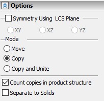
This command (Create Subassembly) is available in the assembly Structure window and in the context menu of the fragments selected in the "3D Model" window. This command allows you to change the hierarchy of fragments in the assembly structure: place the fragments in the subassembly by changing their level to n-1, where n is the current fragment level.

In the "Assembly Structure" window, select the fragments to be placed in a separate subassembly and click the Actions ![]() icon, select the Create Subassembly command from the list of commands.
icon, select the Create Subassembly command from the list of commands.

The create detail dialog box appears (for more information, see "Detail creation dialog"). To create a new assembly unit, select the option Create Fragment.

You can see the assembly structure changes in the "3D Model" Window The selected fragments moved to a lower level, and a new assembly unit appeared in their place.

The fragments in the new subassembly will retain their transformations according to the assembly from which they were placed in the new subassembly. Reference elements will retain the source of reference geometry (Geometry Source) and the source parameters of the document (Documents Get Parameters from).
If the fragment moved to the level down was adaptive to the assembly (subassembly), it will cease to be adaptive, because the link "Assembly → fragment of the first level" will be broken.
Parts That Do Not Depend on Assembly
The design principle of "Top-down" implies the dependence of the parts from the assembly. However, this dependence is not always possible. For example, you may know exactly which geometry elements of one fragment will define the elements of another, but you don't know in which assembly you can make them dependent on each other. Such a case is possible when the final structure of the assembly is not yet clear, or it is hidden because of the secrecy. Then you can assign a link not through the assembly, but directly between the files. In any case, you should specify the link between the fragments via the assembly file. But in this case it can be temporary. An example of the use of the temporary assembly files can be viewed in the section about transformations of the fragment in the assembly.
Keep in mind that the use of temporary assemblies, or the unavailability of the assembly when editing fragments, should be caused by a real production or design need. In all other cases, it is not recommended to apply the temporary assembly and remove the assemblies. The very concept of "Top-down" design implies the presence of an assembly that defines all the parts included in it.
Let's consider the case when the "Box Cover" fragment depends on the geometry of the Box Body regardless of the Box assembly. Suppose we have an assembly "Box", in which one fragment is "Box Body". Create a new fragment "Box Cover" with the command <FM> Create 3D Fragment, and enable its editing in the context of the assembly. Create two reference elements using the <3RE> Reference Element command: select the top face that defines the fixing edge and the face on which the cover will rest. In the properties window, specify Geometry Source: initial fragment.
|
|
Exit the context of the assembly with saving ![]() . Check through the "Assembly Structure" window how the reference elements were created. From the "Assembly Structure" window, you can see that the fragment "Box Cover" has two referenced elements. After selecting the update option from the source fragment (in this case we could choose the update option from the fragment of the first level, because the result would be the same), we specified that Geometry Source is in the "Box Body" file. Source parameters (Get Parameters from the Document) is always the assembly file in the context of which the reference element was created, (you can find detailed information in the section about transformations of the fragment in the assembly).
. Check through the "Assembly Structure" window how the reference elements were created. From the "Assembly Structure" window, you can see that the fragment "Box Cover" has two referenced elements. After selecting the update option from the source fragment (in this case we could choose the update option from the fragment of the first level, because the result would be the same), we specified that Geometry Source is in the "Box Body" file. Source parameters (Get Parameters from the Document) is always the assembly file in the context of which the reference element was created, (you can find detailed information in the section about transformations of the fragment in the assembly).

When creating a reference element, you did not specify that the geometry source is in the assembly (you did not select the Geometry Source option: assembly). In the reference element there is no "assembly → fragment of the first level" link and the reference element was not included in the geometric parameters, i.e. the generated fragment is not adaptive. As you can see, the Create geometric adaptive parameters for reference element option is not available when you change the geometry source from assembly variant to another variant.

Let's create a Box Cover geometry based on the created reference elements.
If we change the "Box Body" fragment, the "Box Cover" fragment will convert its geometry according to Box Body changes only after updating the reference elements. You can do it in the "Assembly Structure" window, as shown earlier.
When the source geometry does not depend on the assembly file, we can delete the assembly file, the fragments will not lose their links via the reference elements.
For example, delete the file "Box" and create a new assembly file "Box 2". Insert fragments "Cover Box" and "Box Body" into using the <3F> 3D Insert Fragment command. In the "Assembly Structure" window of the new "Box 2" assembly, you can see that the "Box Cover" fragment as before contains reference elements whose geometry source is the "Box Body" fragment. |
|
The source of the document parameters (Get Document Parameters from) is still the deleted "Box" file. This means that if we needed to move, rotate, or scale a fragment for correct positioning in the assembly, we would have to do it again. In this case, no transformation parameters were passed from the remote assembly to the fragment, because we did not move or scale the fragments in the assembly.

Change the length of the Box Body in the new "Box 2" assembly, and update the reference elements through the "Assembly Structure" window.

The new assembly file "Box 2" has been updated as if we were working in the original assembly file "Box".
Unload Geometry with Possibility of Subsequent Updates
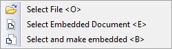
If the body was created in an assembly (subassembly of any level), you can unload it by making a part. To do this, select the Detail command in the context menu of the body. You should select the third or fourth option of the body unload in the Detail > Unload command, for a fragment to be created as a fragment with a geometric parameters, but without reference elements
●Unload a detail (the Detail>Unload command) with the option Create Part Operation (Save Solid to File that can be updated when assembly changes).
●Unload part (the Detail>Unload command) with the Create Associative Part Operation (Save Solid to File and replace it with Fragment Operation) option.
The build tree is not available in the fragment files created by the third or fourth variant of the Unload command. The geometry in the files is an external model. You can edit the geometry of the fragments only when you change the geometry of the body in the assembly file. The possibility to edit fragment files after they are created on the basis of bodies in the assembly is given by the Detail > Create command.
It is rational to apply the options for the creation of fragments in the assembly described in this subsection in the case, when unloading the body using the command Detail > Create leads to recursions (more information about recursions and their removing can be found in the section "Eliminating recursions using reference elements"). The other case is when you want to make a part dependent on an assembly without using reference elements.
The two ways for creating fragments are not recommended if the fragments you are creating are subassemblies.
Again consider the example, when we designed the Box Clip in the Box Cover file fragment and want to create a fragment based on Box Clip body (this example was already discussed in the section "Create details using Detail > Create command"). Call the context menu of the Body Clip body and select the command Detail > Unload. |
|

In the appeared dialog, specify the Create Part Operation (Save Solid to File that can be updated when assembly changes) option. The principle of entering the name of the file and the choice of the prototype is similar to the principle when working with dialog of fragment creation. In the "Unload Dialog" section you can see a brief information about this dialog.
As a result of the command, an adaptive fragment will appear. In the "3D Model" window you can see that an adaptive fragment appeared in the Body Clip body structure.

A fragment of the first level also appeared in the "Assembly Structure" window of the "Box Cover" file. This fragment contains geometric parameter "Imported Solid_1" and does not contain reference elements.

The Reference Elements Tab.

The presence of the "Imported Solid_1" geometric parameter provides the link of the "Box Clip" fragment file with the "Box Cover" assembly, i.e. the link with the file from which the geometry was unloaded. You can transfer changes made to the source body in the assembly file to the fragment file. To do this, select the Update command.
Only changes made for operations, which are located in the body tree before unloading, will be transferred to the fragment file.
For example, we can change the length of the Box Clip by changing the profile of the extrusion operation, which is located before unloading. After changing the geometry of the clip body, call the Update command via the context menu.
|
|

After executing the Update command, the fragment file will be updated according to the body changes in the assembly and saved.

You cannot transfer changes in the geometry of the body, performed due to operations that are in the body tree after unloading, to the fragment file. For example, if we make a hole in the Body Clip and the operation is located after unloading, the Update command will not pass the changes to the fragment file.
|
|
We can add operations in an unloaded tree of the body. To do this, call the context menu of the last operation of the body and select the Rollback Model command. Call a rollback command for the Body Clip.

Add a hole to the Box Clip geometry. As you can see from the picture, hole was added to the tree of body operations. To finish editing the body, you need to call the context menu for body operations or call the context menu in the free space of the 3D scene, and select Finish Rollback.
|
|
A hole created in this way can be passed to the fragment. To do this, select the Detail > Update command in the context menu of the clip body. The fragment file will be updated, modified according to the assembly, and saved.

We can pass the changes made in the fragment to the assembly. To do this, use the command Detail > Restore Associativity.
Make a hole in the Box Clip, not in the assembly, but in the fragment file. To do this, open the Box Clip fragment file and make a hole in it, then save the fragment file. In the "Box Cover" assembly, call the command Detail > Restore Associativity in the context menu of the Body Clip body.

As a result of the operation, the changes made in the fragment will be transferred to the assembly.

The Detail > Restore Associativity command will be available in the context menu only if changes have been made to the fragment file.
Consider the fourth option to unload Create Associative Part Operation (Save Solid to File and replace it with Fragment Operation).
As in the previous case, call the command Unload through the context menu of the Body Clip body in the assembly, but this time specify the fourth option.

Displaying the created fragment in the "3D Model" and "Assembly Structure" windows is similar to the previous variant of unloading.
As in the previous case, the fragment has no reference elements and has a geometric parameter ("Imported Solid_1"). The Geometric parameter connects the fragment with the assembly.
As in the previous case, the generated fragment has a link only to the assembly file from which it was unloaded.
As in the previous case, we can make changes to the body operations that were created before the unload and then use the Update command to upload them to the fragment file.
As in the previous case, we can add operations to the body tree before unloading – using the Rollback Model command.
Unlike the previous unload option, changes made to the fragment will be automatically transferred to the assembly. That is, to update the assembly according to the changes in the fragment file, we do not need to use the command Detail > Restore Associativity.
Make changes to the clip fragment: create a hole, then save the fragment. If you open the file "Box Cover" then, as in the case of changing all the fragments, you will be asked about updating the assembly. After the update is confirmed, the fragment in the assembly will be updated.

Through the "Assembly Structure" window, you can specify to re-insert a part or subassembly.
Any fragment of any level will be re-inserted as a fragment of the first level for the assembly file that we are currently editing.
Let's continue the example with the Box assembly. We need to insert the Box Clip to all remaining positions. A fragment of Box Clip is a fragment of the second level within the subassembly "Box Cover". If we want the "Box Clip" fragment to be a second-level fragment included in the "Box Cover" subassembly when re-inserting, we need to open the "Box Cover" fragment. If we want to position the fragment "Box Clip" only on the basis of binding to the geometry of the cover – you can just open the fragment file "Box Cover". If you want to bind to all elements of the general assembly when positioning the clip, you should open the "Box Cover" fragment in the context of the "Box" assembly. All elements of the general assembly, to which was bind a fragment of the "Box Clip", will be reference elements for "Box Cover" fragment.
Let’s consider both cases.
Open the "Box" file, open the "Box" fragment in the context of the Box assembly. Turn off the selection of assembly elements by making the icon ![]() inactive. In this case, the binding will be only to the cover elements.
inactive. In this case, the binding will be only to the cover elements.
In the "Assembly Structure" window, call the context menu for the "Box Clip" fragment and choose the Additional>Repeat insertion command.

Next, according to the LCS insertion principle, as for the "Bottom-up" assembly, determine the position of the fragment. Specify the source LCS on the axis of the Box Clip and the target LCS at the axis of the Box Cover foot. Turn around the axes to determine the correct position of the Box Clip.

Exit the context of the assembly with saving ![]() . The second fragment of the second level appeared in the "Assembly Structure" window. It has a link to the same source file of the "Box Clip" fragment and the same reference elements, because reference elements belong to the source file of the fragment.
. The second fragment of the second level appeared in the "Assembly Structure" window. It has a link to the same source file of the "Box Clip" fragment and the same reference elements, because reference elements belong to the source file of the fragment.

Once again, open the "Box Cover" fragment in the context of the assembly. Now turn on the selection of assembly elements, by making the icon ![]() active. In the "Assembly Structure" window, use the context menu of the fragment to specify re-insertion. Select the source LCS at the top of the rectangular Box Clip hole, and the target LCS at the top of the Box Body edge (that is, the assembly element in which you are working). Rotations around the axes determine the correct position of the clip.
active. In the "Assembly Structure" window, use the context menu of the fragment to specify re-insertion. Select the source LCS at the top of the rectangular Box Clip hole, and the target LCS at the top of the Box Body edge (that is, the assembly element in which you are working). Rotations around the axes determine the correct position of the clip.

In the "Assembly Structure" window you can see that a new fragment of Box Clip has appeared. It is important to note that the fragment "Box Cover" has a new reference element. This reference element was created automatically when the vertex was selected to specify the target LCS when the fragment was inserted. Since the vertices of the edge Box Body in the fragment "Box Cover" is not present, it should be borrowed from the assembly. A corresponding reference element was created.

Since the "Box Cover" fragment is a first-level fragment of the assembly, the new reference element is also a geometric parameter of the fragment.

The Detail > Duplicate command is available in the context menu of each fragment. The duplicate makes both a copy of the fragment in the assembly, with all the values of its parameters (External Variables and Geometric Parameters), and a copy of the source file on the disk, also with all the values of the parameters. That is, it creates two identical links in the assembly: "fragment in assembly → source fragment file", storing parameter values both in the assembly and in the source file.
Considered an example. You have the Housing assembly, where you already placed all the screws D4хL6. Each fragment has the same source file "Pan Head Cross Recess Screw ISO 7045". In addition, there is one screw D5хL8, and it also has a source file - "Pan Head Cross Recess Screw ISO 7045".

The file "Pan Head Cross Recess Screw ISO 7045" has external variables. The values of variables in the source file and in the fragments of screws D4хL6 and screw D5хL8 are different. Create a duplicate link "Fragment Screw D5хL8 → Pan Head Cross Recess Screw ISO 7045.grb". To do this, call the context menu of the D5хL8 screw fragment in the "Assembly Structure" window. Select the command Detail > Duplicate.

A dialog box appears in which you specify the name of the new source file and its location.

As a result, a new fragment was created, exactly repeating the original, and a new source file, also exactly repeating all the parameters of the duplicate.

A new fragment will have the same location in the assembly as the original, i.e. in this case, there will be two screws in a hole. The position of the fragment, as well as all its parameters, can be changed.
Positioning, Scaling, and Variation of Fragments in Assembly (Fragment Transformations)
In "Top-down" design, a reference element is created in the context of an assembly based on the geometry of the fragments, taking into account the transformations of the fragment in the assembly (i.e., its movements, rotations, scaling, and the values of its parameters). Accordingly, each reference element needs to "know" not only the Source Geometry but also "know" the transformation of the source-geometry in the assembly. Information about the transformations of the fragment, on the basis of the geometry of which the reference element was created, is located in the assembly file, since it is the assembly that determines the position and execution of all fragments. Therefore, for each reference element, you specify not only the source file where the Geometry Source is located, but also the assembly file in the context of which the reference element was created. For a reference element, the assembly file is the source of the document parameters (Get Document Parameters from).
The source of the document parameters (Get Document Parameters from) will always be the assembly file in the context of which the reference element was created.
Considered an example. We have the Holder assembly. For example, while you do not understand exactly how it should be located Bracket on the Support and do not understand what should be the length of the Bracket. Therefore, you set the length of the Bracket using external variable, and the Bracket in the assembly is located approximately.

You need to design a Hanger. Let's create two Reference Elements that will be edges of Bracket holes. Since you have only approximate assembly, then you should specify the file, which will contain the source geometry – a fragment of the bracket. To do this, we specify Geometry Source: initial fragment.
|
|
As a result, the created fragment will have a geometry source of reference elements in the "Bracket" file, and the source (Get Document Parameters from) of parameters (transformations) of the fragment will be an assembly file "Holder".

Let's create a Hanger geometry.

Suppose that our assembly was incorrect. The length of the Bracket should be different, and its location also need to be changed. Create a new "Corrected Holder" assembly. In the new assembly change the position of the Bracket and change its length by changing the value of the external variable, which determines the length of the Bracket. Insert the fragment "Hanger". The fragment will be located according to the location in the old assembly. In addition, since the fragment "Bracket" changed its geometry only in the assembly (according to the value of the external variable), and in the source file remained the original length, the Hanger is not located correctly along the Support and along the Bracket. |
|

The example shows that the geometric reference itself is preserved, but the fragment "Hanger" has no information about transformations of a fragment of "Bracket" in the new assembly, because the assembly file "Holder" remained the source (Get from Document Parameters) of parameters (transformations) of the fragment.

This example only shows the importance of the information contained in the assembly. Keep in mind that the use of temporary assemblies, or the unavailability of the assembly when editing fragments, should be caused by a real production or design need. In all other cases, it is not recommended to apply the temporary assembly and remove the assemblies. The very concept of "Top-down" design implies the presence of an assembly that defines all the parts included in it.
Variations of Fragments Relations with Assembly when Designing "Top-down"
When designing "Top-down", the fragments should depend on the assembly. In T-FLEX CAD, there are three mechanisms by which such a relation can be made:
●Reference Element,
●Geometric Parameter,
●External Variable.
External variables and geometric parameters of adaptive fragments can be used in the "Bottom-up" design, and are not a new feature of T-FLEX CAD. The use of external variables and adaptive fragments is described in the appropriate subsections: "Parametric Relation definition" and "Adaptive 3D Fragments".
Creating a Reference Element is a feature of T-FLEX CAD that is specifically designed to provide link from assembly to fragments (or directly between fragments). The reference element can be placed in the geometric parameter of the fragment – then such a fragment becomes adaptive.
The presence of a Reference Element in the Geometric Parameter makes it possible to receive a new adaptive fragment variation when changing the geometry in the assembly, without updating the reference elements in the fragment files.
Consider the possible combinations of reference elements and geometric parameters of the fragments in the "Top-down" design.
●The fragment is non-adaptive, without reference elements (a frequent case when a fragment is inserted into an assembly on a "Bottom-up" design basis with the use of LCS).
●The fragment is adaptive, containing reference elements in geometric parameters (a frequent case when working with fragments of the first level).
●Adaptive fragment containing geometric parameters (outdated methods of detail unloading)
●Adaptive fragment containing reference elements both in geometric parameters and reference elements not in geometric parameters (a common case when working with fragments in the context of different assemblies).
●The fragment is non-adaptive, containing reference elements (a frequent case when working with fragments of the second and deeper levels).
In the assembly Structure and 3D model Windows, fragments with geometric parameters are specified using a special icon.
The presence or absence of geometric parameters of fragments of the second and lower levels cannot be seen in the "Assembly Structure" window. To do this, use the 3D model window, or open a fragment in the context of the subassembly for which it is a fragment of the first level.
|
Non-adaptive Fragment or Fragment Containing Only Reference Elements |
|
Adaptive fragment containing geometric parameters or reference elements in geometric parameters |
|
The second and lower level fragment in the "Assembly Structure" window |
External variables of the fragment, its geometrical parameters and reference elements can be seen in the "Assembly Structure" window.


If the fragment was not created as adaptive, it can be made adaptive by adding a geometric parameter.
If the fragment was created without reference elements, you can add them by opening the fragment in the context of the assembly and using the <3RE> Reference Element command.
If a fragment does not have reference elements in geometric parameters, you can create them by opening the fragment in the context of the assembly in which it is a fragment of the first level and using the <3RE> Reference Element command.
Any fragment can be made non–adaptive. To do so, you need to delete all its geometric parameters.
In other words, we can change the variants of the fragment dependence on the assembly.
Reference elements-cannot be removed, because they are based on the body of the fragment.
You can prevent a reference element from being updated (either when it is created, or later through its context menu in the "3D model" window).In this case the fragment will behave as a fragment without a reference element, since further borrowing of the source geometry for the reference will be prohibited.
A non-adaptive fragments without reference elements are files with geometry elements (or even without them) that do not have Geometric Parameters.
You can create a non-adaptive fragment without reference elements ![]() in the following ways:
in the following ways:
●Using the <FM > Create a 3D fragment command without using reference elements or other geometric parameters of the fragment.
●Use the Detail > Create command with the Create Fragment option. A construction should not depend on other constructions in the assembly.
●<3F> 3D Insert Fragment is a standard command when designing "Bottom-up".
Non-adaptive fragments without reference elements should be created only if the part is not going to change. The created fragment should be the main one in the assembly, all other fragments should depend on it, and the fragment itself should not depend on changes in other fragments. In the case when changes in the assembly are made using "Bottom-up" design.
The fragment is adaptive and contains reference elements in geometric parameters. Such a fragment can be created if the reference element automatically is automatically added to the geometric parameters – detailed information is given in the "Reference element in geometric parameters" section.
The geometric parameters of any adaptive fragment can be seen in the properties window of the 3D Fragment command. To call this command for an already created fragment, you can select ![]() Edit from the fragment context menu.
Edit from the fragment context menu.

The fragment is adaptive, containing geometrical parameters. This type of fragment provides a link only between the assembly and the first level fragment.
When designing "Top-down", the primary binding element of the assembly is the reference element. You can also use other tools to link a fragment to an assembly: variables and geometric parameters. As mentioned above, a reference element can be a geometric parameter, but in this case we consider a fragment that does not contain reference elements at all, but contains only geometric parameters. The case when during "Top-down" designing the fragment has no reference elements, but has geometric parameters can occur if:
●the user select the last two options of the Detail > Unload command;
●the user calls the <FM> Create 3D Fragment command, but does not create reference elements, and using the <3U> Adaptive Fragment command, creates geometric parameters for the fragment;
●the user uses the Bottom-up design principle and inserts a fragment (<3F> Insert 3D Fragment) that is created as an adaptive Fragment (<3U> Adaptive Fragment).
The adaptive fragment is adaptive and contains reference elements in the geometric parameters and in the reference elements not in the geometric parameters. Fragments, in which part of the reference elements were in the geometric parameters, and part is not is a possible case. Such fragments can be created as follows.
●If you create reference elements for a fragment in the context of different assemblies, one of which is a fragment of the first level.
●When you edit a fragment in the context of an assembly for which the fragment is a first-level fragment, you specify Geometry Source in the assembly for part of the reference elements, and specify Geometry Source in the assembly for part in the fragments.
●When you create a reference element in a context of any other assembly (it is not the assembly, where the fragment was created) for a fragment received using the Detail > Create command with Create Adaptive Fragment option.
You must remember that adaptive fragments change their geometry according to the value of the geometric parameters in the assembly, so the execution of the geometry in the fragment file and the execution of the fragment in the assembly may differ. If you want a fragment that has a reference element not in geometric parameters, to change its geometry in the assembly, you must update the reference element in the fragment file. Accordingly, those reference elements that are in the geometric parameters of the fragment will change the geometry of the fragment without updating the references in the fragment file, and those that are not in the geometric parameters will change the geometry of the fragment only after the update.
If a fragment contains a part of the references in the geometric parameters, and some – out of geometrical parameters, it should be understood that simultaneously two different communication methods of a fragment and the assembly are used. If you change the source geometry of reference elements you should take care of the changes order and order of the reference elements updates .
If you have problems updating the geometry of a fragment, you can remove the reference element from the geometry parameters. To remove a reference element from the geometric parameters, open the fragment's context menu (via the "3D model" window or the "Assembly Structure" window) and select |
|
Non-adaptive fragment with reference elements. This variant of the fragment is one of the most common. This fragment can be created in the following cases:
●the user creates a fragment in the context of an assembly for which the fragment is a second-level fragment or lower;
●the user specifies the source geometry not in the assembly, but in the fragments;
●the user cancels the Create geometric adaptive parameters option when creating a reference element;
●the user selected the Create Fragment option in the Detail > Create command;
the user removed reference elements from the geometric parameters of the fragment.
See also: Reference Element, "Assembly Structure" Window, Create 3D Fragment, Detail>Create, Detail>Unload


