User Element Coordinate System


User Element Coordinate System |
|
By default, all drawing elements will be created in the page coordinate system (CS). To create drawing elements in a user coordinate system, you should create a user CS using the LCS command:
Icon |
Ribbon |
|---|---|
|
Draw → Style → LCS |
Keyboard |
Textual Menu |
<FV> и <L> |
Construct > Fixing Vector > LCS |
The created CS is defined by two nodes that define its OX axis. The first selected node will be the center of the CS. The second node will determine the direction of the OX axis. The OY axis is perpendicular to the OX axis. You may edit nodes to change the CS position: translation in the drawing plane and rotation.
All bindings that are available for construction and graphic lines are available during CS creation. If you selected characteristic points of graphic line during the CS creation, free nodes will be automatically created in the same position.
A dialog for the CS creation will appear after two nodes selection.
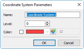
You should specify Level, Color (their description is given above) and Name for the CS.
The created CS is not an active CS that defines coordinates of the created drawing elements. You should select it before constructions creation to make the CS active.
You can select a CS in the list of a drawing coordinate systems. The list can be found in the Ribbon in the Style group near the icon for a user CS creation. All coordinate systems for the current page and workplane are displayed in the list.
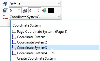
The active CS is shown in the Ribbon. On the page or workplane it will be displayed with thick lines.
You can call a user CS creation in the bottom of the list.
The selected CS will determine coordinates of the created constructions. The selected CS determines constructions only on the current page or workplane like the default CS. The created CS will not be available on other pages or workplanes.
User CS is not displayed in the hidden construction lines mode, is not printed and is not exported to third-party formats.
Changes of a user CS location will cause position changes for all constructions created according to this CS.
Projection Coordinate System
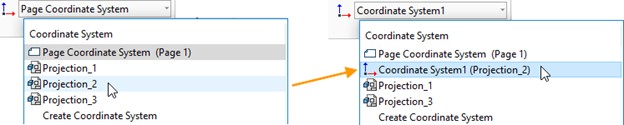
The projection CS is a special type of a user CS. You can create a CS for each projection on a drawing. The projection CS is created using the list of coordinate systems You should select the required projection in the list and a CS will be created for it automatically.
If you are editing a projection, it is convenient to perform editing in accordance with the user CS of the projection. The CS and all the constructions will be moved in accordance with the projection rotation or movement.