Welds in 3D Model


Welds in 3D Model |
|
The weld modeling commands of T-FLEX CAD allow creating welds not only in a 2D drawing, but also within a 3D model. Welds appear in the 3D scene as special “cosmetic” bodies with a specific texture.
You can make an annotation for a 3D weld just like you do for a weld in a 2D drawing The annotation can be created directly in the 3D model (it will be a 3D leader note), or on a 2D projection of such model.
When you create the table of welds on one of 2D pages of a given document, the 3D welds are entered in it along with the 2D welds.
Basic Information about 3D Welds
A 3D weld can be created by various means. All methods of creating 3D welds can be classified in groups:
-3D welds created on faces of the 3D model;
-3D welds created by guides: “by one guide” and “by three guides”;
-3D welds created on edges, 3D paths, 3D profiles, and operations;
-3D welds created by already existing 3D welds.
For 3D welds created by edges and by guides a new “cosmetic” body is created in the 3D scene. These welds do not influence the remaining part of the 3D model and are It is not entered in the 3D model history. In the 3D model tree, a 3D weld body is put into a separate “Welds” folder.
The “WeldMaterial” material from the standard T-FLEX CAD materials library is used for the weld body.
If a 3D weld is created by other methods, the new body will not be created. The weld will be represented in the 3D scene by the model elements on which it is based.
By using various methods of creating 3D welds in T-FLEX CAD, you can simulate various types of welds in the 3D model.
For any 3D weld it is possible to specify to which weld type it belongs. The type determines all basic characteristics of the weld (type of weld joint, structural elements, annotation). The type of the weld does not depend on the way the weld was created.
The weld type is created as a separate model element. The weld types defined in the current document are common across both the 2D and 3D welds. A detailed description of weld types is available in the “Weld” chapter.
You do not have to specify the type of a 3D weld. Such a 3D weld would be called nonstandard. A nonstandard 3D weld is not entered in the welds table. Besides that, nonstandard 3D welds are not displayed in the welds tree of the “Welds” window.
The nonstandard 3D welds can be used to decorate the 3D model. For example, suppose, the user wants to draw a weld on the model simply to make it look more realistic, without an intention to create weld documentation in the future. In such a case, it may not be justifiable to spend time on creating a weld type. You can simply define a nonstandard 3D weld in the 3D model.
Please distinguish between the “nonstandard” 3D weld and a 3D weld created by the nonstandard weld type, whose parameters were custom-defined by the user. The 3D weld of a nonstandard type is entered in the welds table.
Methods of Creating 3D Welds
Creating 3D Welds on Faces
There are three methods to create a 3D weld on faces of the 3D model:
-Creating a continuous fillet weld;
-Creating an intermittent fillet weld;
-Creating a butt weld.
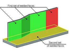
In all such cases, the weld is created based on two sets of faces being welded. The sets define the faces that must be “connected” by the weld. The number of faces in the sets doesn't have to match. The selected faces must belong to one or two Bodies.
Continuous Fillet Weld
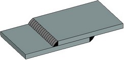
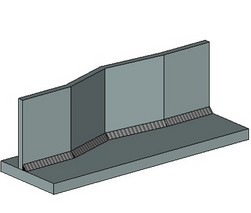
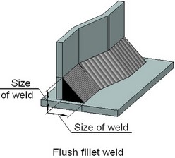
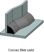
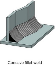
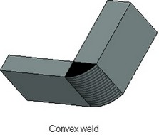
When creating a continuous fillet weld, you need to select two sets of faces being welded, the size of weld and the contour type (flush, convex, concave). The result will be a weld between the surfaces of the specified sets of faces, whose size will correspond to the defined size of weld.
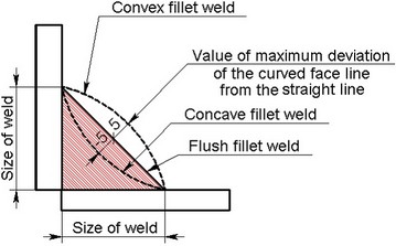
The size of weld is counted from the line of faces' intersection (see the figures). The weld contour being created is specified as the maximum deviation of the curved face line of the weld being created from the straight line. A positive deviation value means convexity of the weld, whereas negative – the concavity. Zero value corresponds to the “Flush” contour.
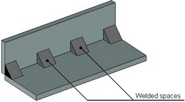
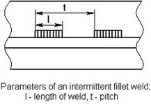
Intermittent Fillet Weld
An intermittent fillet weld is a kind of a fillet weld in which the continuity is broken by recurring unwelded spaces. Therefore, it is generally created in the same way as a continuous fillet weld. Additionally, you need to specify the length of weld and pitch. Please note that for some types of welds, these parameters may be predefined by the type itself (if so required by the applicable standards, such as GOST). In this case, the values defined for the weld, override the values prescribed by this weld type.
Butt Weld
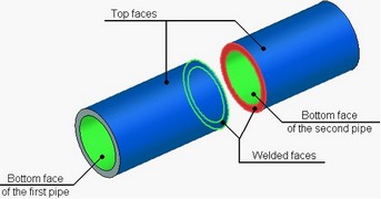
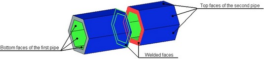
A butt weld connects the entire surface of the two sets of faces being welded. To ensure the correct orientation of the butt weld, you need to additionally specify the top and bottom faces for each set of faces being welded. Those define the required correspondence to construct the weld body. Specify the top and bottom faces by picking ones among those having common edges with the faces being welded.
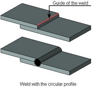
For example, when creating a butt weld between two pipes of the round section shape, you select the outer cylindrical faces of both bodies as the top faces. The bottom faces in this case will be the inner cylindrical faces. Or, you can do the opposite, as far as the outer face of one body matches with the outer face of the other body, and so do the inner faces.
|
|
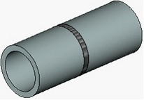
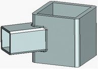
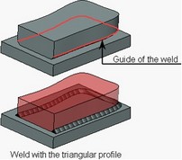
When creating a butt weld between two pipes with a noncircular section shape, select all outer faces of both pipes as the top faces, and all inner faces - as the bottom faces. At the same time, if several top faces are specified on each of the bodies, then the order of selecting faces on one body must match the order of selecting faces on the other body. The same is true in the case of selecting several bottom faces on each of the bodies.
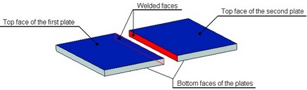
When creating a butt weld between two plates, you select the top and bottom faces as the ones, along which the weld will go. Please note that the top face on one plate must be on the same side as the top face on the other plate.
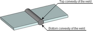
In the case of the butt weld, you can specify the contour type (flush, convex, concave) on either side of the parts being welded (that is, on the sides of the top and bottom faces). The weld contour from each sides of weld is specified as the maximum deviation of the curved face line of the weld from the straight line.
Creating 3D Weld by Guides
Weld Created by One Guide
When creating the weld by one guide, the body of the weld is created by translation of the weld’s profile along the arbitrary guide. The guide of the weld can be closed.
As a guide, the user can select edges, 3D paths, 3D profiles, etc. It is also possible to define the guide by a group of 3D elements (edges, paths, etc.) on condition that all selected elements form a continuous sequence.
The shape of the profile is selected from two options offered by the system: circle or isosceles triangle. For the circular profile, the user defines the radius, for the triangular profile – the size of the leg and the size of the angle between the legs.
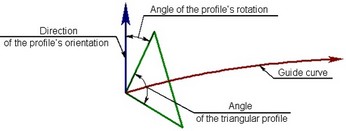
For specifying precise orientation of the triangular profile, the user has to define direction of the profile’s orientation and the angle of the profile’s rotation with respect to this direction. When creating the weld, the vertex of the triangle is superposed with a point on the guide, and one of the sides of the triangle is superposed with the given direction vector, and after that the profile is rotated through a required angle.
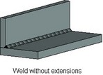
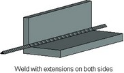
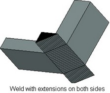
The length of the created weld is equal to the length of the guide. In cases where it is desirable to create the weld longer than the guide, the user can specify the magnitude of extensions at the ends of the guide. The body of the weld will be elongated along the tangent to the guide at its end points by a specified extension length.
Weld Created by Three Guides
For creating the weld of this kind, three guides must be specified. The body of the weld, triangular in cross-section, is formed in such a way that its lateral edges coincide with the guides.
For the guide, the user can select edges, 3D paths, 3D profiles, etc. It is also possible to define the guides by a group of 3D elements (edges, paths, etc.) on condition that all selected elements of one guide form a continuous sequence.
The length of the created weld is equal to the length of the first guide. In cases where it is desirable to create the weld longer than the guide, the user can specify the magnitude of extensions at the ends of the guide. The body of the weld will be elongated (by a parallel shift of the end sections) by a specified extension length.
For the weld by three guides it is possible to specify the contour type (flush, convex, concave) for the side lying between the first and the second guides.
Creating 3D Welds on Edges, 3D Paths, 3D Profiles, and Operations
A 3D weld created on edges, 3D paths, 3D profiles, and operations, can be used in the cases when the required appearance of the weld cannot be achieved by building it on the model faces. It serves to indicate that some existing 3D model elements represent welds. The supply more information with the created composite weld, you can specify, what parts it connects. Please note that such a 3D weld cannot be nonstandard.
When the 3D weld is created, no additional “cosmetic” weld body is created in the 3D scene. You can still “see” such a weld – as you select it in the welds window, the respective 3D objects will be highlighted in the 3D scene.
If necessary, you can manually assign the “WeldMaterial” material to the body representing a 3D weld.
A 3D weld created on edges, 3D paths, 3D profiles, and operations, is entered into the table of welds along with other types of welds. The length of a composite weld is determined in the automatic calculation mode as the sum of the perimeters or lengths of all 3D model elements that are involved in it, except bodies (operations). The bodies that are involved in a composite weld, are not accounted for when automatically calculating its length.
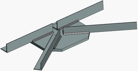
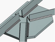
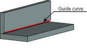
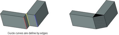
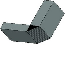
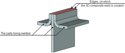
As an example, consider creating a flange-face weld. Suppose, we need to create a weld that connects three parts (see the figure below). Neither the fillet nor the butt 3D weld is suitable in this case. We will therefore create a 3D weld on two edges, and will additionally specify what bodies must be connected by this weld.
Creating 3D Welds by Existing 3D Welds
A 3D weld can be created based on a set of already existing 3D welds. Such a weld cannot be nonstandard. Just like in the previous case, no additional body is created in the 3D scene when such a 3D weld is created.
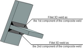
As an example of creating such a weld consider creating in T-FLEX CAD a two-sided Tee-weld. A Tee-weld can be imitated by a pair of fillet welds. To make this pair of welds work as a single weld in the future, you need to additionally join them into one weld.
To add more information to the created composite weld, you can specify, what parts it connects.
The length of the composite weld in the automatic calculation mode is determined as the sum of all 3D welds that it includes. The properties of a composite weld created from a set of 3D welds are determined by the type specified for this composite weld. The parameters of the source welds are ignored. Please also note that the table of welds generally includes both the source 3D welds and the resulting weld, which is based on them. To avoid duplicates, we recommend using nonstandard 3D welds as the source welds. In this case, those will not be entered in the welds table.
Creating 3D Weld
A 3D weld is created with the command “W3: Create 3D Weld”:
Icon |
Ribbon |
|---|---|
|
Assembly → Assembly → Weld → Weld |
Keyboard |
Textual Menu |
<W3> |
Tools > Weld >3D Weld |
To create a 3D weld, you need to:
1.define type of the weld being created;
2.select the method of creating the weld;
3.select the source geometrical objects for the weld (depends on the weld creation method);
4.define the weld length (if necessary);
5.define additional weld parameters (the size of weld, the contour type or any other parameters depending on the weld type);
6.confirm the weld creation.
Selecting Type of 3D Weld
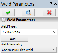
The type of the weld being created is selected in the command's properties window, in the “Weld Type” drop-down list. The list contains all types of welds created in the current T-FLEX CAD document.
If the required weld type is not yet created, you can use the button [Add…]. Clicking this button starts the command of the new weld type creation. When the type is created, the system returns to the weld creation command. The created weld type will be automatically selected. If no weld types are defined in the current document at the time of starting the “W3: Create 3D Weld” command, then the weld type creation command will be launched automatically. |
|
How to create a new weld type is described in the “Weld” chapter.
Besides the weld types that the user created, the “Weld Type” list contains an additional option “Non Standard”. It is used to create nonstandard 3D welds.
Selecting the Method of Creating a 3D Weld
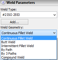
You select a method of creating a 3D weld using the “Weld Type” drop-down list in the command's properties window. To create a 3D weld on model faces, you need to select one of the following entries in the list – “Continuous Fillet Weld” (creation of a fillet weld), “Intermittent Fillet Weld” (creation of an intermittent fillet weld), “Butt Weld” (creation of a butt weld). Welds by one guide or three guides can be created by selecting, from the list, the options “By Curve” and “By Three Paths”, respectively. To create a 3D weld based on existing entities of the 3D model (except faces) you shall select the option “Compound Weld”. |
|
The “Compound Weld” option is not available in the list, if the “Weld Type” field specifies “Non Standard”.
Selecting the Source Geometrical Objects of a Weld. Advanced Weld Parameters
The source geometrical objects selection for the weld being created, as well as additional weld parameters, depend on the method of creating this weld. Therefore, we will review different methods of creating a 3D weld separately.
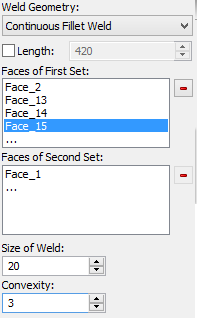
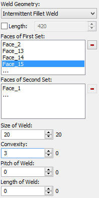
Welds on faces. Continuous and intermittent fillet welds
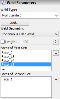
As you select the “Continuous Fillet Weld” or “Intermittent Fillet Weld” item in the list, the following options become available in the command's automenu to select the two sets of faces being welded:
|
<1> |
Select Faces of First Set |
|
<2> |
Select Faces of Second Set |
The selected faces are entered in the lists “Faces of First Set” and “Faces of Second Set”. To remove some face from a selected set, pick it in the respective list by clicking ![]() , and then click the button
, and then click the button ![]() .
.
The size of weld can be defined using the same-name parameter in the properties window.
The contour type of the weld defined by parameter “Convexity”. This parameter define the value of maximum deviation of the curved face line of the weld from the straight line. A positive deviation value means convexity of the weld, whereas negative – the concavity. Zero value corresponds to the flat contour.
In the case of an intermittent fillet weld, you can additionally specify pitch and length of weld.
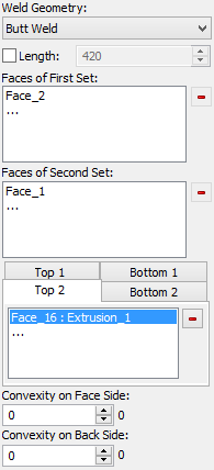
Welds on faces. Butt Weld
The two sets of welded faces in the butt weld are selected using the same options
The selected faces are entered in the lists “Top 1”, “Top 2”, “Bottom 1”, “Bottom 2”. To remove some face from the selection, pick it in the respective list by clicking In the case of the butt weld, you can also specify “Convexity on Face Side” (that is, the contur type of the weld on the side of the top faces) and “Convexity on Back Side” (the the contur type of the weld on the side of the bottom faces) in the properties window. |
|
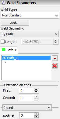
Weld by Created by Guide
For creating the weld by a guide, the user should select the option “By Path” found in the list “Weld type”. After that in the automenu the option for selecting the guide will be available:
|
<T> |
Select 1st Guide |
The pull down list of this option contains the filters for selection of 3D objects – loops, edges, 3D paths, 3D profiles, etc. The objects selected as the elements of the guide are put into the list “Path 1” in the command’s properties window. To cancel selection of a 3D object, select it in the list with the help of If you want to cancel selection of the guide entirely, press the button
If the selected guide is not long enough, it is possible to increase the weld’s length by specifying the magnitude of the extensions. This can be done with the help of parameters of the group “End Extensions” found in the command’s properties window. Parameters’ group found in the lower part of the section “Weld” of the properties window allows the user to select the type of the weld’s profile: Round (circle) or Triangular. When selecting the circular profile it is necessary to indicate its radius. For triangular profile you need to specify the length of the lateral side of the triangle (parameter “Size of Weld”), angle between the sides of the triangle (“Angle”) and the angle of rotation with respect to the direction of the profile orientation (“Rotation”). The direction of the triangular profile orientation can be specified with the help of the following option of the automenu:
To cancel selected direction, use the following option:
|
|
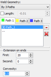
Weld Created by Three Guides
For creating the weld by three guides, the user should select the option “By Three Paths” found in the list “Weld type”. After that in the automenu the following options for selecting the guides will be available:
|
<T> |
Select First Guide Curve |
|
<D> |
Cancel Selection of First Guide Curve |
|
<W> |
Select Second Guide Curve |
|
<K> |
Cancel Selection of Second Guide Curve |
|
<A> |
Select Third Guide Curve |
|
<M> |
Cancel Selection of Third Guide Curve |
Selected objects are put into the list “Path 1”, “Path 2”, “Path 3” in the command’s properties window. The length of the created weld is equal to the length of the first guide. You can increase the length by specifying the magnitude of extensions at the ends of the path with the help of the parameters of the group “End extensions”. In the dialog of the properties window for the weld created by three guides, it is also possible to specify the contur type of the weld (“Convexity”). |
|
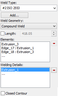
Welds on edges, 3D paths, 3D profiles, operations, and 3D welds
To create a weld on edges, 3D paths, 3D profiles, operations and other existing 3D welds, you need to set the option “Compound Weld” in the “Weld Type” list. After that, the options to select the 3D model source objects will become available in the automenu:
|
<C> |
Select weld elements |
The drop-down list of this operation contains the filters to select 3D objects – 3D welds, edges, 3D paths, 3D profiles, and operations. The objects selected as the members of the 3D weld are entered in the “Elements” list in the command's properties window. To remove some 3D object from the selected, you need to pick it in this list by clicking The parts that will be connected by this created weld can be specified with the option:
You can additionally specify that the composed weld makes a closed loop, by setting the flag “Closed Contour”. |
|
Defining Weld Length
The method of calculating the weld length is determined by the state of the “Length” flag. When the flag is off, the weld length is calculated by the system automatically. When the flag is enabled, the length value is defined by the user in the input box next to the flag.