Main Concepts of Edge Blend |
  
|
Main Concepts of Edge Blend |
|
This sub-chapter describes basic principles of geometry creation. The detailed description of operation creation interface can be found in other sub-chapters.
Subjects of the edge blending operation are edges of a body (solid or surface). Additionally, some vertices may be selected on the involved edges in order to specify particulars of the intended shape. The set of the automenu options allows selection of various objects, besides the edges, such as loops, faces, vertices and operations. This helps selecting certain common combinations of edges. Thus, for instance, by selecting a vertex, we select all the edges meeting at that vertex. Selecting a loop by the definition means selection of the sequence of edges making this loop. Selecting a face results in selection of all its surrounding edges (single or multiple loops). Selecting a solid automatically makes selected all its edges appropriate for blending.
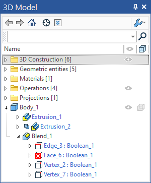
It is very important to understand how the information is maintained about the original elements subjected to blending. These original elements selected for blending are remembered in the model history. Thus, in case a face was selected, a reference to this face is recorded in the model tree. In this case, the set of edges to blend is built anew at each regeneration. This way of selecting brings the advantage of having a quite robust operation. If topology of the selected object changes (for example, the number of edges changes), the operation will be correctly regenerated with the new set of edges of the involved object. Otherwise, if a specific edge were selected that would later disappear, then the system would output an error.
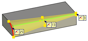
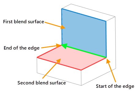
Each selected edge has a direction indicated by an arrow. Other blend-defining conditions depend on this direction. The arrow tail defines the edge start. According to an agreement, the surface on the right-hand side of the edge, as looked in the arrow direction, is conventionally called the first blend surface, and the one on the left-hand side – the second.
Types of blend
Rounding is the most commonly used type of blending. A surface is created along the selected edge, providing a smooth transition from one face to the other. A condition holds that any normal cross section of this surface with respect to the edge is an arc of the specified radius.
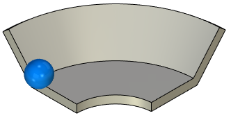
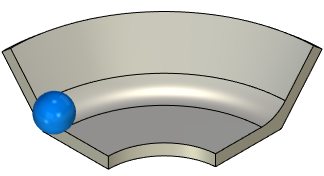
To easily realize how the rounding surface is generated, imagine a ball of the specified radius rolling along the selected edge, touching the faces adjacent to the edge. The trace of the ball represents the blend surface for the given edge. The surface may be defined in a single or multiple passes, particularly, if different edges are rounded with different radii. Complex spline surfaces may be constructed to join multiple edge blends.
The operation may add or remove material, depending on whether the angle between the faces of the blending edge is convex or concave.
The rolling ball must be touching at least one of the adjacent faces. Otherwise, rounding will fail and the system will output an error.
This type of rounding creates a surface of a variable radius. A list of critical points is defined. A certain value of the rounding radius can be set at each of these points. Each point position is defined as percentage of the total edge length. Initially, this list contains two points at 0% and 100% of the edge length.
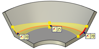
If several edges are selected, then the point positions are defined as percentage of the total chain length for all consequently adjoined edges. The edge joints are not required to be smooth. A single direction is used for the whole chain of edges. It is defined by the direction of the first edge in the chain.
When defining this type of blending along a closed loop of edges, always make sure that the start and end point radii are equal.
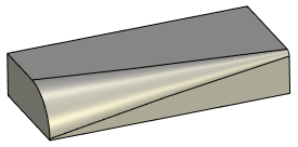
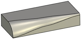
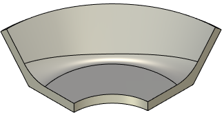
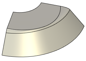
The change in the rounding radius between points can be Linear or Smooth. In the Linear case, the change in the radius is described with a broken line (the radius changes linearly from one point to another). In the Smooth case – the change in the radius is specified by a curve having a horizontal tangent at the start and end points.
|
|
Linear change of radius |
Smooth change of radius |
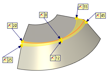
A special mode is provided for processing certain cases, that allows specifying own variable rounding parameters for each individual edge. When processing a smooth chain of edges in this mode, make sure the radii are equal at the meeting ends of the adjacent edges.
This type of rounding allows creation of advanced blend surfaces. Size and shape of the blend surface is defined by the offsets from the first and the second faces (as conventionally denoted), and by the convexity coefficient (Rho) value.
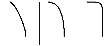
Depending on the convexity coefficient (Rho) value all resulting surfaces are divided in three groups:
•0 < K < 0.5
Blend surface cross section have elliptical shape.
•K = 0.5
•Blend surface cross section have parabolic shape.
•0.5 < K < 1
•Blend surface cross section have hyperbolic shape.
|
||
0 < K < 0.5 |
K = 0.5 |
0.5 < K < 1 |
The shape of the surface can be defined at any point on the edge or on the chain of edges. The list is managed in the same way as in the case of the circular variable-radius rounding. The change in the rounding radius between points can be also Linear or Smooth as in the circular variable-radius rounding.
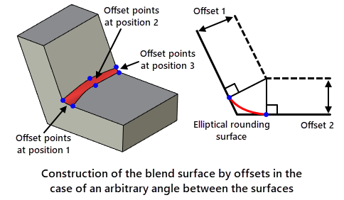
The offsets from the faces define the boundaries of the blend surface. The algorithm for constructing a blending surface with a variable elliptical radius is illustrated in the following figures:
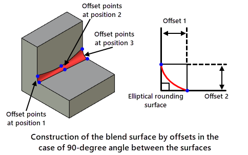
1. An offset surface is constructed at the distance Offset 1 from the second face.
2. Another offset surface is constructed at the distance Offset 2 from the first face.
3. The intersection line between the two offsets is projected on the original faces in normal direction, thus defining the boundaries of the blend surface.
In the special case of blending two flat orthogonal faces, this means the distance from the blended edge to the side boundary of the blend surface is equal to the value of the offset.
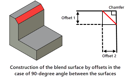
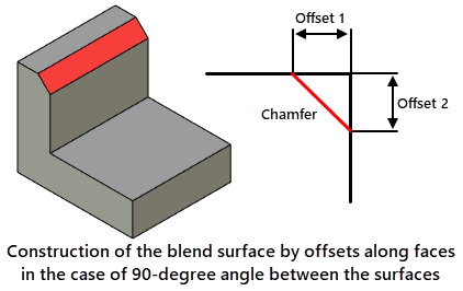
A chamfer can be constructed along a selected set of edges. A chamfer can be defined by two offsets from the adjacent faces. The algorithm for constructing a chamfer by offsets is similar to rounding algorithm with variable elliptical radius and is illustrated in the following figures:

The chamfer can be specified by length and angle. The algorithm for constructing a chamfer by length and angle is illustrated in the following figures:
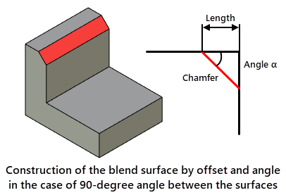
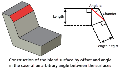
For a given angle, the second length value is calculated as the product of the first and the tangent of the angle. Further calculations are performed as in the algorithm for constructing a chamfer by two offsets.
Chamfer by offsets along faces
A chamfer can be specified with two offsets along adjacent faces. The algorithm for constructing a chamfer by offset along the faces is illustrated in the following figures:
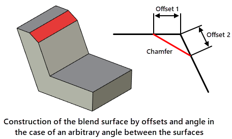
From the point of intersection of the faces, offset values are measured along each face, and a blending surface is created using the points at the ends of the offset.
When the angle between the surfaces is 90 degrees, the results obtained with the offset chamfer and the offset chamfer along the faces are identical. Differences appear only with an arbitrary value of the angle between the surfaces.