Main Concepts of Vertex Blend |
  
|
Main Concepts of Vertex Blend |
|
This sub-chapter describes basic principles of geometry creation. The detailed description of operation creation interface can be found in other sub-chapters.
Automatic vertex blending
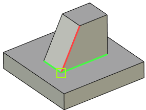
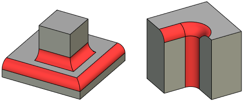
A single operation can be used for blending all edges meeting at one vertex. The edges can be of either the convex or the concave type. Simultaneous blending of all edges meeting at one vertex automatically involves blending of vertex itself.
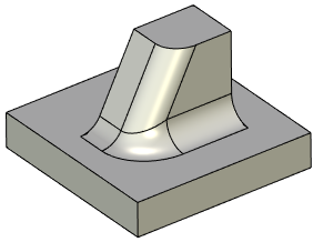
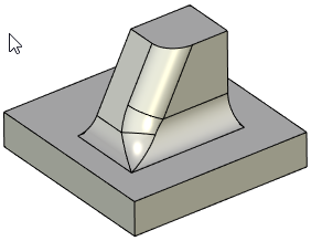
A shape of blending geometry at a vertex can be changed by choosing a different Edge Processing Order: Default (the order of smoothing edges is determined by the system independently), Concave blends first, Convex blends first, On edges of minority convexity first, On edges of majority convexity first. Please note: in order to control a shape of blending at a vertex, it is necessary to select this vertex in addition to the edges when creating blending.
This option is not available for chamfers.
|
|
Red edge - convex, Green edges - concave, Green square - blended vertex |
|
|
|
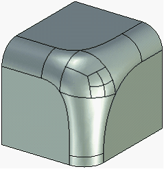
Convex blends first |
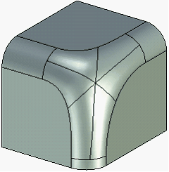
Concave blends first |
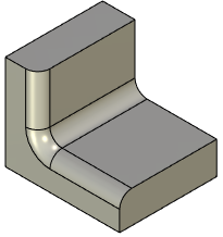
To avoid the vertex blending, do the edge blending by two blending operations, first blending any two edges meeting at a vertex, and then the third edge, by disabling the Propagate option. The result in this case will look as shown here:
|
|
First blend |
Second blend |
Sometimes it is impossible to blend all edges at once, and the system outputs an error. In this case, try creating the intended blends by steps.
The above implies that proper handling of the operation leads to successful blending of practically any edges of any model.
It is recommended to use as few operations as possible when blending several edges of one solid. Prefer blending a set of edges by one operation, rather than by a number of operations one edge at a time. With this approach, the model regeneration is much faster, and the blending algorithm most likely performs best.
Blending two of three edges meeting at a vertex
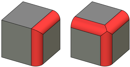
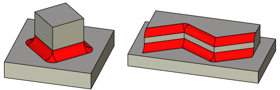
When blending a pair of edges of the same convexity, two blend surfaces are constructed – one per edge. The vertex is not blended in this case; rather, new edges are created at intersections of blend surfaces.
However, when blending a pair of edges of opposite convexity, the vertex where the edges meet is automatically blended.
Blending a pair of edges of the opposite convexity is impossible for chamfers.
|
|
Blending a pair of edges of the same convexity |
Blending a pair of edges of the opposite convexity |
Processing of vertices joining edges of different convexity
Consider the special case when three edges of different convexity meet at a vertex.
When blending two edges of the same convexity, you could use the option of also blending their common vertex. This would require selecting the vertex as well.
This option is not available for chamfers.
The results are shown below:
Rounding with an offset from vertex
When rounding a group of edges meeting at a vertex, you can specify an offset from this vertex. The following figures demonstrate how this offsetting affects the shape of the resulting blend:
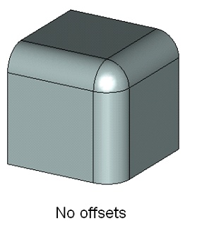
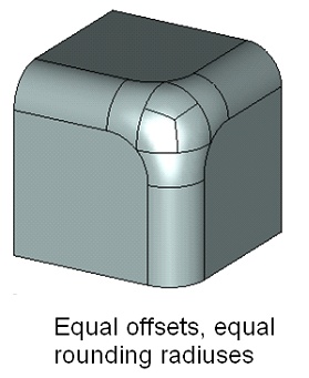
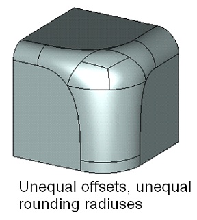
You can see that the offset defines a zone of smooth transition from one blend surface into the other. The specified radius of rounding is not guaranteed in the transitional zone. The transitional zone can be created with or without special transitional faces - collar faces.
|
|
Blend with collar faces |
Blend without collar faces |
The Offset parameter can be specified at any edge's start and end. However, offsetting can be done only for a set of three or more edges meeting at a vertex. Some of the meeting edges may be directed away and some towards the vertex. That said, make sure the offsets are defined on the vertex side for all edges. If an edge connects two vertices, each subject to offsetting, then the offsets are to be defined for both the edge start and end.
In some cases, T-FLEX CAD system allows automatic synchronization of the Offset parameters for the edges with opposite direction. This happens, for instance, when selecting a group of edges by clicking a vertex. (Detailed description of the steps for defining offsets can be found in other sub-chapters).
Special dynamic manipulators are provided for marking offsets on the edges while defining the operation parameters. Their presence and location help easily realize the offset parameters and modify, if necessary, by the mouse.