Create Vertex Blend |
  
|
Create Vertex Blend |
|
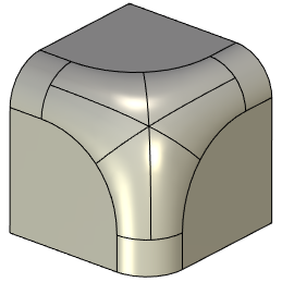
Vertex is blended automatically when blending all edges which meet at this vertex. Additionally you can specify Y-Shape, Offsets, Vertex Chamfer or Edge Processing Order parameters if necessary.
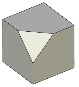
When rounding two edges of a same convexity, meeting at a vertex with a third non-blended edge of an opposite convexity, such vertex is not rounded automatically. However, you can set rounding of such vertex manually. For this you have to select a vertex. Rounding will be applied to selected vertex using radii specified for the adjusting edges.
This option is available only for constant-radius and variable-radius rounding.
For constant-radius rounding this option works only if adjusting edges are rounded using equal radius values.
For variable-radius rounding this option works if both of following conditions are met:
•parameters are specified individually for each edge (Common Properties checkbox is disabled);
•equal radius values are set for adjusting edges' ends.
Selecting a vertex for blending
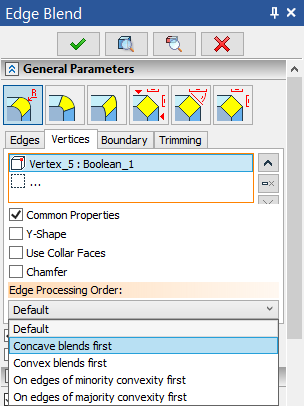
To select a vertex go to the Vertices tab of the General Parameters tab of the Parameters window, or use the following automenu option:
|
<Z> |
Allow vertex selection without edge selection |
 .
.
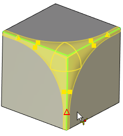
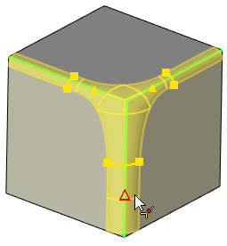
This automenu option and the Vertices tab are linked together: activation of the tab activates the automenu option and vice versa. This mode enables filter for selecting points on the Filter Toolbar. Then you can select a vertex in the 3D scene by moving mouse cursor over it and clicking ![]() . Selected vertex will be displayed in the list. Vertices added to the list are highlighted in green in the 3D scene, current selection is highlighted in red.
. Selected vertex will be displayed in the list. Vertices added to the list are highlighted in green in the 3D scene, current selection is highlighted in red.
Buttons allowing to ![]() Collapse the list,
Collapse the list, ![]() Delete Element from the List or
Delete Element from the List or ![]() Clear the list are located to the right side of the list. Click
Clear the list are located to the right side of the list. Click ![]() on element in the list to select it. Selected element will be highlighted in the list.
on element in the list to select it. Selected element will be highlighted in the list.
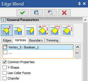
Each row of the list contain an element type icon (vertex), a name of an element and a name of a parent body.
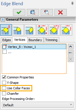
Vertex blend options checkboxes are located below the list.
The Common Properties checkbox (enabled by default) applies same condition of Y-Shape, Use Collar Faces and Chamfer checkboxes as well as selected Edge Processing Order to all elements in the list. Disabling Common Properties for selected element allows to define its parameters independently.
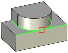
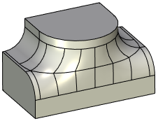
When two edges of opposite convexity are tangent at a vertex where three or more faces meet, a special option is available for blending the vertex - Y-shape. Blend surfaces created using this option are lesser curved in the transitional zone around the vertex, then surfaces created by default.
|
|
|
Blended edges are highlighted in green, vertex selected for Y-shape definition is highlighted in red |
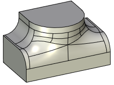
Operation result with Y-Shape disabled |
Operation result with Y-Shape enabled |
This option is available only for constant-radius and variable-radius rounding.
Following steps should be done to create an Y-Shape rounding:
1. Select edges for rounding.
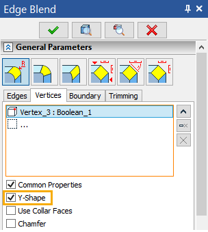
2. Select the vertex for Y-Shape blending.
3. In the list on the Vertices tab, click the vertex and enable the Y-Shape checkbox for it.
If Y-Shape blend can't be constructed in the given vertex, the system will apply default way of blending, ignoring the Y-Shape checkbox.
4. Depending on the selected blend type specify the blending radius for edges using manipulators or in the Parameters window.
5. Finish input ![]() .
.
Defining a rounding with an offset from a vertex
Main concepts of rounding with an offset from a vertex can be found in the corresponding sub-chapter.
This option is available only for constant-radius and variable-radius rounding.
Following steps should be done to create a rounding with an offset from vertex:
1. Select edges for rounding by clicking on a vertex in the mode ![]() of selecting faces, edges and vertices. Zero-value offsets from the selected vertex are automatically set when selecting edges using this way. This is indicated by appearing of offset manipulators. Selected edges will be put in the list on the Edges tab in the Parameters window. The vertex itself won't be put in the list.
of selecting faces, edges and vertices. Zero-value offsets from the selected vertex are automatically set when selecting edges using this way. This is indicated by appearing of offset manipulators. Selected edges will be put in the list on the Edges tab in the Parameters window. The vertex itself won't be put in the list.
2. Specify offset values. This can be done using offset manipulators or by entering values into the Start and End fields of the Offset group located below the edges list.
|
|
Common Properties are enabled for all selected edges |
Common Properties are disabled for the vertical edge |
Initially, the Common Properties checkbox is enabled for all edges. This allows entering equal offsets for all selected edges. Modifying one offset causes all the rest edges assume the same value. This is indicated by the synchronous movement of offset manipulators.
To define different values of the offsets, disable the Common Properties checkbox. This does not have to be done for all edges at once. Individual properties can be set only for some particular edges by disabling Common Properties checkbox only for them. For the rest, the common properties will still be used.
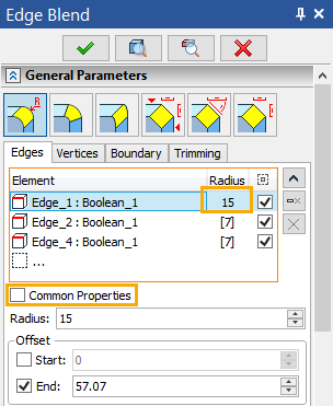
The offset values are displayed in the Start or End fields of the Parameters window - depending on which point of an edge is used as a base for offset. Exact values can be typed in these fields using keyboard. Checkboxes activating the Offset at the start or at the end of an edge are located to the left side of the Start and End fields. When selecting edges by clicking a vertex, the system automatically enables necessary checkboxes for the edges meeting at such vertex. This is done depending on edge direction. Some edges have a Start offset, others - End offset, so that all of them have offsets from the vertex where they meet.
If necessary, you can manually define enable desired offset using these checkboxes. Meanwhile, manipulators can be used for visual control of offset parameters.
3. Depending on the selected blend type specify the blending radius for edges using manipulators or in the Parameters window.
4. By default blending with offsets uses collar faces. If it is necessary to disable collar faces, you need to additionally select the vertex itself. Collar faces are not used on the selected vertices by default. You can Use Collar Faces on selected vertex by enabling the eponymous checkbox.
5. Finish input ![]() .
.
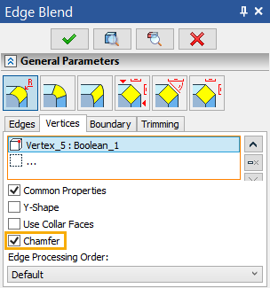
For a vertex at which three or more edges meet it is possible to create a chamfer without chamfering adjacent edges. It cuts body by polygon created using points defined by Offset values for the adjacent edges. In some complex cases the resulting chamfer surface will be curved.
Vertex chamfer can not be created when edges of opposite convexity meet at this vertex or when one of the edges splits tangent faces.
Following steps should be done to create a vertex chamfer:
1. Click ![]() on a vertex in the mode
on a vertex in the mode ![]() of selecting faces, edges and vertices. All edges meeting at this vertex will be added to the list on the Edges tab of the Parameters window. The vertex itself won't be put in the list. Zero-value offsets from the selected vertex are automatically set when selecting edges using this way. This is indicated by appearing of offset manipulators.
of selecting faces, edges and vertices. All edges meeting at this vertex will be added to the list on the Edges tab of the Parameters window. The vertex itself won't be put in the list. Zero-value offsets from the selected vertex are automatically set when selecting edges using this way. This is indicated by appearing of offset manipulators.
Select edges meeting at a single vertex only. Creating chamfers on a multiple vertices in a single operation is impossible.
2. Specify offset values.
This can be done in the same way as for rounding using offset manipulators or in the Parameters window.
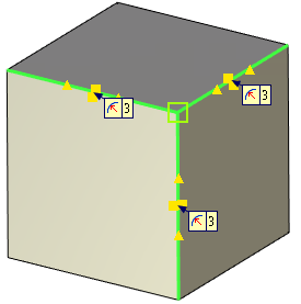
3. Select vertex and enable Chamfer checkbox for it.
It is impossible to select a vertex before setting offset values, because, when offsets are equal to zero, manipulators overlap the vertex
Select a single vertex only - the one where selected edges meet. Creating chamfers on a multiple vertices in a single operation is impossible.
4. Finish input ![]() .
.
Defining edge processing order when blending vertices
This special processing is only applicable for constant-radius rounding.
Main concepts of edge processing order can be found in the corresponding sub-chapter.
Following steps should be done to define an edge processing order:
1.Select edges for rounding.
2.Depending on the selected blend type specify the blending radius for edges using manipulators or in the Parameters window.
3.Select vertex where you want to specify edge processing order
4.For the selected vertex the Edge Processing Order field becomes active. From the drop-down list it is possible to select one of the following options: Default, Concave blends first, Convex blends first, On edges of minority convexity first, On edges of majority convexity first.
5.Finish input ![]() .
.
See also:
•Common options for solid 3D modeling operations