Create Edge Blend |
  
|
Create Edge Blend |
|
Following steps should be done to create an edge blend operation:
1. Select edges for blending.
2. Select Blend Type and define parameters depending on the selected type:
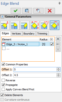
•Chamfer by offsets
•Chamfer by length and angle
•Chamfer by offsets along faces
3. Define Vertex Blend, Boundary Saving, Trimming, Special Options and Overflow Processing if necessary.
4. Use Preview of Operation Result or Preview of Solid Changes if necessary.
5. If blend can not be created using specified parameters use Diagnostics and change parameters.
6. Finish input ![]() .
.
After starting the operation, the element input field is active, allowing you to select all elements suitable for creating the operation.
Upon calling the command the Edges tab on the General Parameters tab of the Parameters window becomes active as well as the corresponding automenu option:
|
<E> |
Select Faces, Edges, Vertices |
This automenu option and the Edges tab are linked together: activation of the tab activates the automenu option and vice versa. This mode enables filters for selecting 3D elements allowed for defining edges on the Filter Toolbar. Then you can select object in the 3D scene by moving mouse cursor over it and clicking ![]() . When selecting elements, pay attention to active filters.
. When selecting elements, pay attention to active filters.
![]()
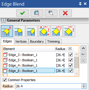
Edges tab contain the list of elements.
Upon selecting an operation all edges of the corresponding body are added to the list. The body itself isn't added to the list.
Upon selecting a vertex all edges meeting at this vertex are added to the list. The vertex itself isn't added to the list.
Using vertex for selecting edges is the only way to automatically enable offsets.
Upon selecting a face it is added to the list and blend parameters are applied to all edges of such face. Remember that selected face will always be considered the first blend surface.
Upon selecting a loop it is added to the list and blend parameters are applied to all edges in a loop. Remember that face framed by a selected loop will always be considered the first blend surface.
The way of selecting edges for blending (directly or using loops and faces) affects operation regeneration upon further changes of initial geometry.
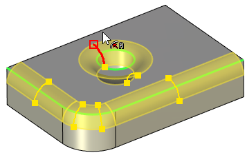
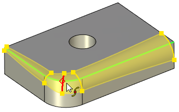
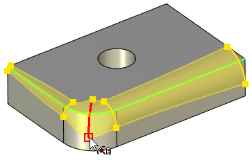
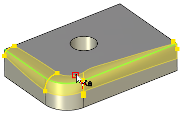
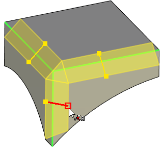
Edges and loops added to the list are highlighted in green in the 3D scene, faces are highlighted in blue, current selection is highlighted in red.
Buttons allowing to ![]() Collapse the list,
Collapse the list, ![]() Delete Element from the List or
Delete Element from the List or ![]() Clear the list are located to the right side of the list. Click
Clear the list are located to the right side of the list. Click ![]() on element in the list to select it. Selected element will be highlighted in the list.
on element in the list to select it. Selected element will be highlighted in the list.
List is represented in a tabular format.
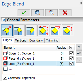
The first column Element contains an element type icon (edge, face or loop), a name of an element and a name of a parent body.
The second column Radius contains one or two numerical values. Depending on the selected blend type such values may represent radii, offset 1 and offset 2 or length. Values could not be edited directly from the list. Use corresponding fields below the list instead. If Common Properties checkbox is enabled for selected element, value in Radius column are displayed in square brackets. Disabling the checkbox removes brackets.
The third column Leave Selected contains the checkbox which applies blend to this particular element. It's enabled by default. Disabling such checkbox will exclude corresponding element from the blend. However excluded element will remain in the list after operation creation.
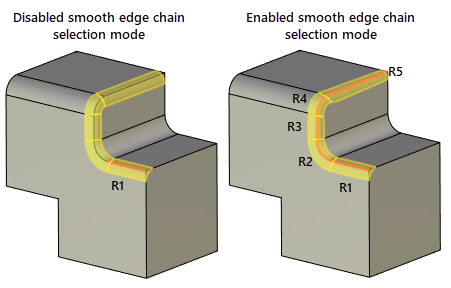
The smooth edge chain selection mode can be activated using the following automenu option:
|
<S> |
Smooth edge chain selection mode |
A smooth chain is a set of edges making an open or closed continuous smooth curve (with a tangent continuity (G1)).
When using this mode, all edges that can make a smooth chain together with the selected edge are added to the list automatically.
Propagating blend on tangent edges.
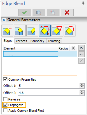
The Propagate checkbox is available for all types of blend. This functionality searches for a smooth continuation of the currently blended edge. A smooth chain may exist originally or form as new edges are created on the blend boundary. In the case of successfully defining a smooth chain the system attempts to propagate the blend along the whole chain.
The automenu option ![]() described above has a similar purpose. However, when selecting an edge with automenu option, all elements of the identified chain are included in the list. When using the Propagate checkbox, the list may not contain all edges of the blended chain, rather, could be just one edge.
described above has a similar purpose. However, when selecting an edge with automenu option, all elements of the identified chain are included in the list. When using the Propagate checkbox, the list may not contain all edges of the blended chain, rather, could be just one edge.
This is important in view of possible topology changes of the model when the smooth chain contents may change. It's enough to select just a single most stable edge of the whole chain to be blended.
If the Common Properties checkbox is disabled for selected edge, the Propagate checkbox is applied to such edge only. Otherwise Propagate checkbox is applied to all edges with Common Properties enabled.
Defining operation parameters.
The operation parameters can be defined at any step of creating the operation. The operation parameters can be defined in the Parameters window or using manipulators.
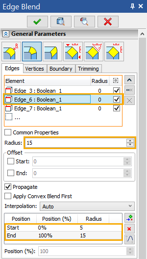
The Parameters window of the Edge Blend operation consists of three sections: General Parameters, Overflow Processing, Options. General Parameters tab itself contains four tabs: Edges, Vertices, Boundary and Trimming. Edges tab may contain different controls depending on selected blend type.
We recommend to begin defining parameters after selecting the elements for blending. As mentioned above, the selected edges, faces, and loops are displayed in the list on the Edges tab. Blending parameters can be defined for a particular object by selecting it in the list. Originally, blend properties are set same for all elements. This is represented by enabled Common Properties checkbox. Disabling this checkbox allows to define individual blending parameters for each element in the list.
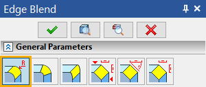
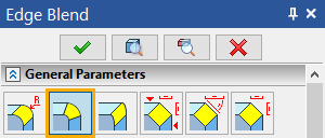
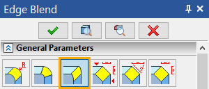
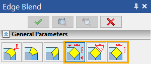
The blend type can be selected from the general parameters.
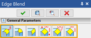
Depending on the blend type, the appropriate controls appear for defining parameters attributed to this type.
Defining a constant-radius rounding
Main concepts of constant-radius rounding can be found in the corresponding sub-chapter.
1. Select edges for rounding. It is convenient to do this first. However, if necessary, objects can be selected at any step of defining the operation.
2. Set the type of blend to Rounding (by default when starting an operation) in the general parameters.
3. Set the Radius of the rounding in the Parameters window or using manipulators.
Initially a single value of the radius is set for all edges processed by one operation. Changing Radius for a single edge results in all the rest instantly adjusting by the same amount. To define individual properties of some edge, select it in the list and disable the Common Properties checkbox. Then, an individual value of the radius can be entered in the Radius field. The radius-controlling manipulators on this edge will become independent from the rest as well.
4. Finish input ![]() .
.
Defining a variable-radius rounding
Main concepts of constant-radius rounding can be found in the corresponding sub-chapter.
1. Select edges for rounding.
2. Select the type Variable (circular) in the general parameters.
The necessary controls will appear for defining the rest of parameters.
3. Next, the set of intermediate points needs to be defined, and radii specified in each point.
Note: initially, the system tries to compose one chain (not necessarily smooth) of all selected edges. If this is impossible, then several chains will be composed. Within each edge chain, the set of points is distributed along the full length of the chain.
The system can automatically compose the chains from the edges with Common Properties checkbox enabled only. If the Common Properties checkbox is disabled for some edge then the whole set of points will be distributed along this edge only, and stay strictly specific to this edge.
If several edges that make a smooth chain are processed simultaneously, with the Common Properties checkbox disabled, make sure the radii on each side of the edge joints are equal.
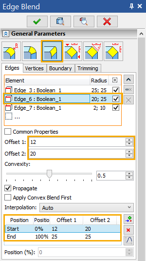
The list of points for defining the radii is located in the lower part of the Edges tab. The list is represented in a tabular format.
First column Position contains a name of a point.
Second column Position (%) contains point's position on an edge expressed as a percentage of an edge's length.
Third column Radius contains value of a blend radius at this point.
Radius and Position (%) values can not be edited directly in the list.
![]() Add after,
Add after, ![]() Delete Element from the List and
Delete Element from the List and ![]() Graph buttons are located on the right side of the list.
Graph buttons are located on the right side of the list.
Initially two points exist in the list – Start and End, at 0% and 100% of the edge (chain) length respectively. These points are always present, and their positions are not modifiable.
To add a new intermediate point, press the ![]() button. A new manipulator will appear on the edge controlling the new point position and the blending radius at this point.
button. A new manipulator will appear on the edge controlling the new point position and the blending radius at this point.
The current position of the selected point is displayed in the Position (%) field below the list of points. Default position of a newly added point is between the point selected add the moment of adding and the next one in the list.
Blend radius at the selected point is displayed in the Radius field below the list of edges.
To adjust the radius and position values without using manipulators, select point in the list and enter values in the aforementioned fields.
Point selected in the list (except Start and End) may be deleted using ![]() button.
button.
Position of the points may be specified via a graph. Use ![]() button. This button will open the graph editing. window. The range of definition by X is 0-100 corresponding to the percentage from the length. The value area is limited with positive numbers only.
button. This button will open the graph editing. window. The range of definition by X is 0-100 corresponding to the percentage from the length. The value area is limited with positive numbers only.
4. Specify the type of the radius change – Linear, Smooth, or a special option – Auto;
The type of the radius change is selected from the Interpolation drop-down. The option Auto is set by default. In this case:
•if only start and end points are specified for the current rounding, the radius change will be calculated by the linear algorithm;
•otherwise (when intermediate points are specified) a smooth algorithm of the radius change is applied.
5. Finish input ![]() .
.
Defining a variable-elliptical rounding
Main concepts of variable-elliptical rounding can be found in the corresponding sub-chapter.
1. Select edges for rounding.
2. Select the type Variable (ellipse) in the general parameters.
The necessary controls will appear for defining the rest of parameters.
3. Next, the set of intermediate points needs to be defined, along with the offsets and convexity coefficient (Rho) values at each point.
Variable-elliptical rounding is based on special points, just like the previous, variable-radius, rounding. The point defining techniques are similar to those described for the variable-radius circular rounding. The difference of this blend type is in the ways of defining the shape of rounding.
In this way of blending, two offsets are defined at each point defining boundaries of the blend at the given cross section, and the convexity coefficient (Rho) value of the cross section curve.
Offset 1 and Offset 2 for selected point may be specified in eponymous fields located below the list of edges or using manipulators. Offsets are also displayed in eponymous columns of the points list. Convexity group of controls is located below Offset 1 and Offset 2 fields. There you can specify convexity coefficient (Rho) using slider or enter the value from keyboard.
In general, without use of manipulators, the following procedure is recommended for defining the blend surface parameters at the points:
•Select the required edge in the list.
•Add required number of intermediate points; define their position on the edge or chain of edges.
•Go through the points of each edge, defining the offsets and convexity coefficient (Rho) values.
4. Specify the type of the radius change – Linear, Smooth, Auto (in the same way as for creating variable-radius circular rounding);
5. Finish input ![]() .
.
Main concepts of chamfers can be found in the corresponding sub-chapters:
•chamfer by offsets along faces
1. Select edges for chamfering.
2. Select the blend type Chamfer (Offsets), Chamfer (Length-Angle) and Chamfer (Offset along Faces).
The necessary controls will appear for defining the rest of parameters.
3. Define chamfer parameters. The set of parameters is different for various chamfer types. The easiest way to roughly set up parameters values is using manipulators. Exact values can be entered in the Parameters window. Offset 1, Offset 2, Length and Angle values could be entered using keyboard in the corresponding fields located below the list of edges.
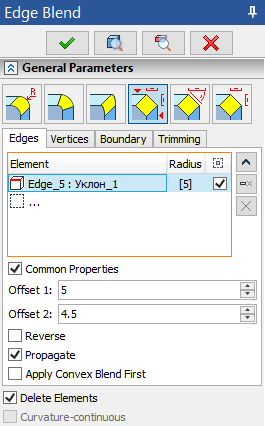
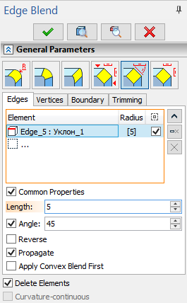
The edge direction determines which face correspond to which offset (or length and angle). The edge direction can be flipped using the Reverse checkbox. This checkbox works individually for each edge and does not depend on the Common Properties checkbox.
When defining chamfer by length and angle, the second marker of the manipulator will be driving the Angle parameter. A special checkbox can be enabled against the Angle field that will block angle modification using manipulator. When this checkbox is enabled, both markers of the manipulator drive the Length while keeping the angle fixed.
4. Confirm the operation by ![]() .
.
See also:
•Common options for solid 3D modeling operations