Special Options of Face Blend |
  
|
Special Options of Face Blend |
|
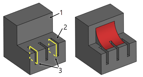
Flat faces and workplanes can be used for limiting the blended area. One limit plane divides the blend surface into two parts leaving just one part in the scene. Total of two limit planes can be defined. The two planes will surround from the two sides the central portion of the.
Source body |
Blend result |
|
|
1. Left wall 2. Right wall 3. Limit planes |
|
It is important to keep in mind that by dividing the blend surface the limit plane is not trimming it. The blend surface is divided along a cross section plane at the point of intersection between the limit plane and the blend spine.
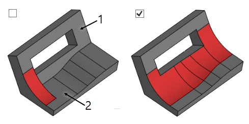
Sometimes, the walls to be blended may include topology insertions (Notches) that cross the line of contact of the blend surface. A special option Notch helps identify such insertions and let blending extend in the affected area trimming the blend surface with the faces adjacent to the wall. Without this option, the blending would stop before the affected area, where the line of contact is crossed.
Face-face blend without notch identification |
Face-face blend with notch identification |
|
|
1. Left wall 2. Right wall |
|
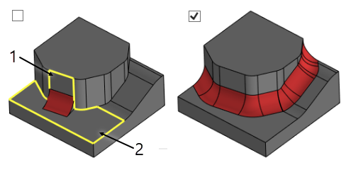
This option allows extending the blend surface on the adjacent faces smoothly connected to the selected walls. This simplifies the operation definition by letting select just one face per a wall. The system will attempt propagating the blend surface on all adjacent faces as far as possible.
Face-face blend without tangential propagation |
Face-face blend with tangential propagation |
|
|
1. Left face 2. Right wall |
|
Propagate option can't be used for disc and isoparametric blend types.
Propagate option is applicable when defining boundary conditions. This allows specifying just one edge for defining boundary conditions if all bounding edges connect in a smooth chain.
Accuracy
The accuracy defines the tolerance to within which the adjacency between faces or edges is considered smooth.
Solutions. Setting a variant of the result topology
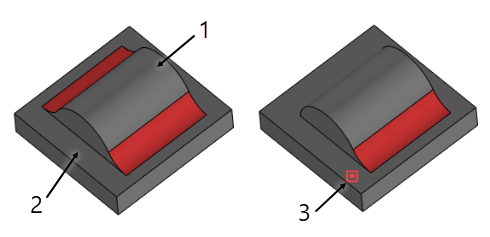
Sometimes more than one face-face blends can be created for the same set of faces. If you select to use all solutions, the command will create all the blends possible. To specify a particular blend result, you can define a 3D node to make the command accept the solution nearest to the selected node.
All solutions of face-face blend |
Face-face blend with solution by 3D node |
|
|
1. Left wall 2. Right wall 3. Selected node |
|
When creating a face-face blend, there is a choice of trimming options for the end boundaries of the blend surface. The geometry of the walls themselves is not disturbed by trimming the blend surface. Total of four trimming options are available:
•No Trimming. When trimming is off, the blend surface is extended beyond the ends of either wall.
•Long Trimming. The blend surface is trimmed by the end boundaries of the longer wall.
•Short Trimming. The blend surface is trimmed by the end boundaries of the shorter wall.
•Faces to Wall. The blend surface is trimmed by the end boundaries of both walls. Meanwhile, the side edge of the blend surface is constructed such as to provide tangency with both side edges of the trimming walls.
First three options can be used for blending surface bodies only.
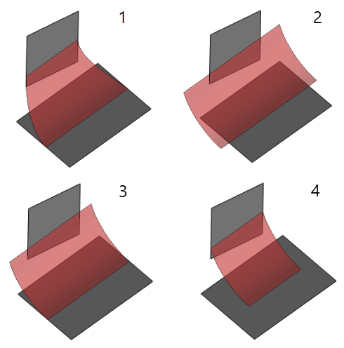
1. Faces to Wall
2. No Trimming
3. Long Trimming
4. Short Trimming
The face-face blend operation can be stored in the model structure in several topological variations. The choice of a topological solution is combined with the wall-trimming interface (the previous topic). Total of four solutions are available:
•Separate Body means neither wall will be trimmed and the blend surface will stay as a standalone surface body. The objects selected for the walls to blend will remain in the model structure in the original state. The blend operation will be represented by a separate surface body – the blend surface.
•Trim Walls trims both walls along the line of contact without attaching the blend to any wall. This solution has a practical meaning only for surface bodies. The model structure will reflect the face-face blend operation alone at the top level. The operations whose faces were selected as walls will be written in the model history one level deeper. Meanwhile, the blend operation will be represented by three surface bodies. This means that if, for instance, the operation Divide Solid is applied to the blend then three separate surface bodies will be created, the two trimmed walls and one blend surface.
•In Left Walls trims both walls and attaches the blend surface to the walls. If blending was done between two different surface bodies then these bodies are united into one by the blend. The operation used as the left wall will further be used as the reference in the model structure.
•Create New Body trims both walls, adds the blend to the walls and creates a solid body if possible. This solution can only be used together with the Faces to Wall trimming option. This option is similar to the previous. The specific of this option is the system attempting to create a solid body. This is done if a check is satisfied for the resulting geometry to form a closed volume.
Inside Tight Corners. Processing curved zones
The algorithm's for processing curved zones allow creating blend's in the areas where the value of the curvature radius of the sidewalls is less than the blend radius. This option is available only for rolling ball blending by a conical section of a constant radius. This functionality is described in more details in the chapter Edge Blend.