Create Face Blend |
  
|
Create Face Blend |
|
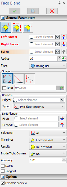
The parameters window and the automenu are used for handling the command and defining necessary components. These work simultaneously and enhance each other. The state of the automenu depends on the operation defining stage and on the purpose and type of the objects being selected. The object selection modes can be manipulated via either the automenu or the parameters window.
To create the operation, follow the following steps:
1. Select type of blending
2. Select first set of faces (the left wall)
3. Select second set of faces (the right wall)
4. Specify blend type (if necessary)
5. Select the spine (if necessary, depending on the blend type)
6. Specify blending mode (if necessary)
7. Specify the shape of the blend cross section (if necessary)
8. Specify geometrical parameters of the blend cross section
9. Specify boundary conditions and overflow processing (optional)
10. Confirm operation creation
Using draggers and decorators
As the face-face blend operation is being defined, the parameters can be specified and various objects selected in the 3D window with the help of auxiliary elements. These elements help quickly review and modify the configuration of the operation being created. Their quantity, shape and size depend on the defined parameters of the operation, on the purpose of the selected objects and on the type and values of the parameters controlled thereby. The elements that control parameters dynamically are called Draggers. The elements that merely display some or other operation parameters are called Decorations.
Draggers are displayed in various colors. By default, the active dragger (the one driven by the mouse at the moment) is drawn red, all the rest - yellow. Decorations are drawn blue by default.
Draggers are used for quick reviewing of the result and correcting it, therefore, the shape follows the actual blend surface with limited accuracy. Dragger does not make an account of all details of the cross section in the case of the surfaces with continuous curvature and is not responding to such settings as Convexity, Softness, etc.
Using draggers with numerous active objects on a low-performance computer may cause delays in the system response. To speed up workflow in this situation, the draggers may be turned off. The off switch for the draggers is located in the Options section of the parameters window.
The following topics review all types of manipulators and decorations for each flavor of face-face blend.
The blending mode can be set at any stage of the operation preparation.
|
Radius |
|
Offset |
|
Width |
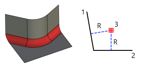
Radius
In this mode, the blend spine is equidistant from both left and right walls by the distance R in all blend surface cross-sections. The distance R can be set as variable with the help of a graph.
|
1. Left wall 2. Right wall 3. Blend spine |
This field interacts with the dragger. Depending on the selected shape of the blend surface, the dragger is drawn as an arc of a circle or as a segment (only when creating a chamfer). The number of draggers depends on the number of faces in the right and left walls. All manipulators change synchronously and are responsible for the same radius parameter.
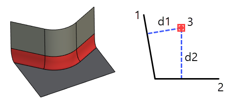
Offset
In this mode, the blend spine is positioned at non-equal distances d1 and d2 from the left and right wall accordingly. These distances can be set as variable with the help of a graph.
|
1. Left wall 2. Right wall 3. Blend spine |
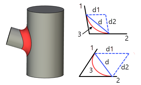
Width
In this mode, the length of the chord d between the left and right walls contact points is constant along the extent of the blend. For this mode you can specify a ratio between the contact point offset d1 on the right wall and the offset d2 on the left wall. The ratio value other than 1.0 creates an asymmetric blend with the constant chord length.
|
1. Left wall 2. Right wall 3. Blend surface |
Set of faces selection
Normally, the operation is defined beginning with selecting the sets of faces between which the blend will be constructed.
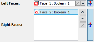
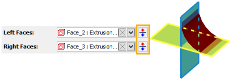
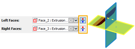
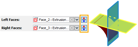
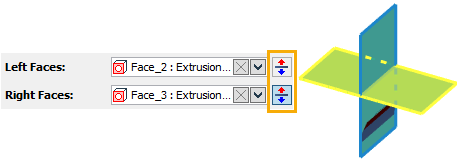
To select a face, select the corresponding input field - Left Faces or Right Faces.
Face selection is done using the mouse in the 3D view window.
The selected faces of the left wall are highlighted in green by default, the right ones - yellow. Settings of the highlighting colors are done in the system customization dialog box. The current face highlighting color is reflected in a color box on the tab tag for each set.
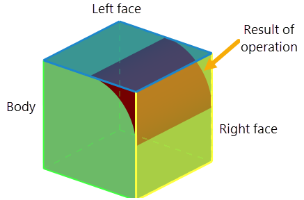
A decorator is drawn in the middle of each face, shaped as an arrow, marking the side of the face adjacent to the blend surface. In a general case, two walls make four quadrants, each being suitable for constructing a blend surface. In order to select a quadrant to create the blend surface, you can use the Reverse ![]() option for each face.
option for each face.
For solid bodies, the direction of an arrow is determined automatically. For surface bodies, the direction of faces has to be controlled manually by the user.
To exclude a face from a wall set, simply select it in the list in the parameters window on the respective field and press Delete Element from the List button.
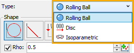
The type of the blend operation can be selected from the pull-down list in the parameters window. One can select any of the three choices: Rolling Ball, Disc, Isoparametric. The system sets the rolling ball type by default.
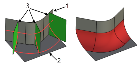
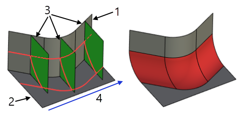
Rolling Ball
The rolling-ball blend has cross-sectional planes that are orthogonal to the walls of the blend.
Source faces |
Rolling ball blend result |
|
|
1. Left wall 2. Right wall 3. Cross-sectional planes |
|
Disk
The disc blend requires a parameter spine. This type of blend has cross-sectional planes that are orthogonal to the specified parameter spine in each point.
Source faces |
Disc blend result |
|
|
1. Left wall 2. Right wall 3. Cross-sectional planes 4. Parameter spine |
|
Isoparametric
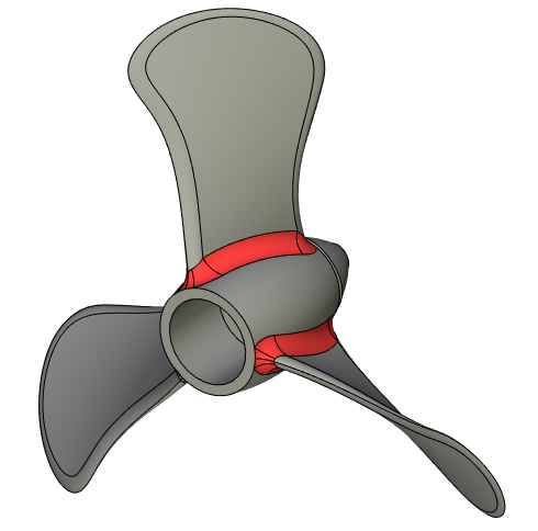
Isoparametric blend is used to make a blend between a turbine blade and a base. This type of blend has cross-sectional planes oriented along the isoparametric lines of the blade surface. Because of this, the blade surface has to be chosen as the first set of faces - a left wall, and the parameter spine must belong to it.
The spine sets the length of the blending, which changes under the influence of the graph. You can use any 3D curve – a 3D path, an edge, a 3D Profile, etc. – as a parameter spine. It always has to be specified for constructing cross-sectional planes of the blend surface for disc and isoparametric blend, and sometimes – for rolling ball blend. Also the parameter spine is necessary for supplying law curves that represent varying radius or offset in cases of variable radius or variable offset blend. The spine works in conjunction with graphs ![]() .
.
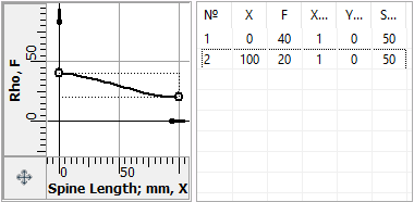
An example of creating blending, taking into account the different lengths of the spines
The graph below uses a cubic spline. At the start point, the blend radius is 40, and at the end point it is 20.
The 3D path is selected in the 3D window or in the model tree using the mouse. The name of the selected 3D path is displayed in the parameters window.
The spine is highlighted in blue.
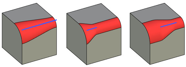
As you can see in the figure, depending on the location of the spine and its length, the blending also changes with the same graph.
Setting a Bounds option
All types of boundary conditions are defined along the specially selected edges.
A list of selected edges is displayed in a special field under the tab.

Switching to this tab of the parameters window from any other mode also activates the edge selection option. The choice of the type of boundary condition is made from the drop-down list. Five choices are available:
|
Two-face tangency |
|
One-face tangency |
|
Two-face inverted tangency |
|
One-face inverted tangency |
|
Cliffedge |
The default offered by the system is Two-face tangency. Each constraining edge requires individual setting of the boundary condition type, in a certain order. First, you need to select a constraining edge in the complete list of edges, and then define (if required) the boundary condition type using the pull-down list.
To remove an edge from the list of constraining edges, press Delete Element From the List button in the parameters window.
One should keep in mind that constraints can work only in connection with compatible geometrical parameters of the blend surface that are defined by the blending mode and cross section shape.
Thus, if the cross section parameters prevent the blend surface from reaching a holdline then the tangency condition on one or both walls is impossible. Vise versa, if an "inverted tangent" constraint is imposed, then the appropriate "radius" of the blend surface is such that the blend is not reaching the holdline or the wall itself in the zone of the constraint validity.
It follows from the above that often draggers stop working on a blend surface constrained to certain boundary conditions. For example, when creating an "inverted tangent" blend surface that does not reach the walls initially, the draggers are not displayed. Vise versa, when creating a "tangent to walls" blend surface that does not fit amid the walls then the dragger reflects the largest arc fitting amid the walls.
See the detailed description of each type of blending boundary processing in the Special Options of Face Blend Operation chapter.
Setting the Limit Planes option
After enabling the option in the 3D window, workplanes and planar faces will become available for selection. The selection is made in the 3D window or in the model tree using the mouse.
When a limit plane is selected, blue decorations are drawn to indicate it. The decoration is a rectangle lying on the limit plane. The size of the rectangle is calculated based on the dimensions of the right and left walls. Arrows are drawn from the vertices of the rectangle perpendicular to the limit plane. The arrows indicate which side of the limit plane the blend surface will be left on.
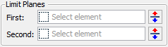
After selecting the first or second limit plane in the parameters window, instead of the inscription not selected, the Reverse check box appears to change the direction of the arrows.
If you want to use only one limit plane, but you need to specify only the First plane. Specify both the First and Second limit planes only when you want to use two limit planes at the same time.
See the detailed description of this option in the Special Options of Face Blend Operation chapter.
Setting a Notch and Tangent options
Attributes are provided in the parameters window for turning on notch handling and tangent propagation. These parameters are accessible for use with all types of blend.
![]()
See the detailed description of these options in the Special Options of Face Blend Operation chapter.
Setting a Solutions option
After selecting a point, its name is written in the operation parameters window. Further, the user is required to explicitly indicate whether the system should use the solution for the 3D node, or use all the received solutions. Solution type is selected from the drop-down list. There are two options available for selection:
|
All |
|
Use Adjusting Point |
The Use Adjusting Point allows you to quickly change the solution type without canceling the selection of an auxiliary 3D node.
See the detailed description of this option in the Special Options of Face Blend Operation chapter.
Setting a Trimming option
The type of end face processing of the blending surface is selected in the parameters window. There are 4 options to choose from:
|
Faces to Wall |
|
No Trimming |
|
Long Trimming |
|
Short Trimming |
By default, the system offers the option Faces to Wall.
See the detailed description of this option in the Special Options of Face Blend Operation chapter.
Setting a Result option
The result topology option is selected in the parameters window. A total of 4 options are available for selection:
|
Separate Body |
|
Trim Walls |
|
In Left Walls |
|
Create New Body |
By default, the system offers the option In Left Wall.
See the detailed description of this option in the Special Options of Face Blend Operation chapter.
Setting the Insight Tight Corners option
The choice of processing for curved zones is selected in the parameters window. A total of 4 options are available for selection:
|
No |
|
Tight Blends |
|
Tight Faces |
|
Tight Partial |
By default, the system offers the No option.
See the detailed description of this option in the Special Options of Face Blend Operation chapter.
To create a "curve-face" blend you must specify:
•set of faces of solid/surface body as a left or right wall of the blend. The second wall is not defined;
•set of smoothly conjugate edges of the wire body (3D profile, 3D path) as a boundary condition;
•radius of the blend;
•option for the final result topology (only the Separate Body or In Left Wall).
All other parameters of the operation in this mode are not used.
As in the general case, for selecting faces it is necessary to either activate one of the tabs Left/Right in the parameters window.
Option for the final result topology is determined by the Result drop-down list in the parameters window. For this mode of blend, you can use only two options: Separate Body and In Left Wall.
Option In Left Wall can only be set if the original set of faces belongs to a surface body. In this case, the resulting body is attached to the original surface body, regardless of which wall has been set in operation - the left or right.