3D Entities and Operations


3D Entities and Operations |
|
A 3D model creation implies building solid or sheet 3D objects describing a certain volume or surface in the 3D space. The creation and further modification of such objects is done by means of operations.
Operation is any step of creating a 3D model that leads to emergence of a new or modifications in an already existing solid or sheet geometrical object. A separate command is provided in T-FLEX CAD for each operation. The names of operation creating commands correspond to an operation's purpose.
The operations that result in new solid/sheet 3D objects will be referred to as basic operations (extrusion, rotation, sweep, loft, etc.). The operations that alter geometry and modify already existing solid/sheet objects will be referred to as modifier operations (blend, shell, Boolean, etc.).
The geometry base for most basic operations is provided by 3D construction elements. 3D construction elements are auxiliary elements of a 3D model that are used for creating three-dimensional contours, defining spatial orientation, determining directions, vectors, axes, trajectories, etc. A separate command is provided for creating each such element.
Some operations (for example, the operations for creating 3D arrays) can be both basic and modifier operations, depending on the source data and parameter settings.
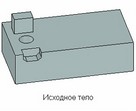
Any solid or sheet 3D object in the 3D scene corresponds to a special element in the 3D model structure, which is Body. The "Body" element is introduced for user convenience: once a new geometrical object is created by the first (basic) operation (solid or sheet body), it can be handled in the future as a permanent element in the 3D model structure.
Body is created automatically upon creating a solid or sheet 3D object by a basic operation, and is maintained as long as the given object exists. The geometry of the original volume or surface may change (as a result of applying modifier operations), but it always refers to the same Body that defines parameters of this geometrical object: name, material, color, rendering settings (mesh density, wireframe display).
A 3D model can contain an unlimited number of Bodies.
In some commands, Bodies can be used as separate elements. In such a case, the source object will be the body of the last operation in the creation history of the given Body. For example, when creating a 2D projection, a specific Body can be selected for projecting. This would be convenient, if the first design stage was making the drawing of the part's workpiece or a set thereof, while the second - modifications of this model by additional operations. In this way, the drawing reflects on all future modifications to this part.
In this manual, the term "Body" (with capital "B") means specifically a 3D model structure element. The lowercase inscription "body" will be used for a quick reference to the geometrical object, which is a volume or surface in the 3D scene.
3D Construction Entities
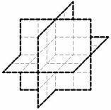
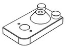
Workplane is an entity that helps defining the required data for 3D operations, and, first of all, creating 3D profiles. A 3D model cannot be built without creating a workplane. Workplanes can be specified in 2D or 3D window based on various references, such as the 2D drawing views, projections of entities in a 3D model, or the 3D entities themselves, including other workplanes. |
|
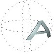
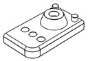
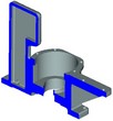
Worksurface serves similar functional purposes as the workplanes, providing a non-planar geometrical basis for further design. A worksurface can be a cylinder, a sphere, or a torus. |
|
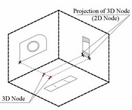
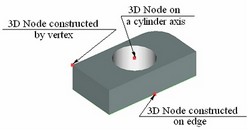
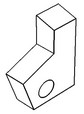
3D node is one of the basic construction entities used for representing a point in the three-dimensional space. There are several ways of creating 3D nodes. A 3D node can be specified, for instance, as a characteristic point on a body, referencing a vertex, an edge, or a face. It also can be located by using absolute coordinates or offsets from other 3D nodes. 3D nodes can also be specified using the nodes from the two-dimensional drawing, and workplanes. In this way, the 3D node will be defined by selecting one node on a workplane, or two nodes on two different workplanes that are related by having a common projection. |
|
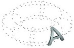
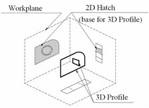
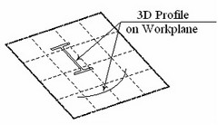
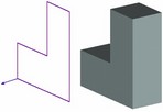
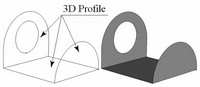
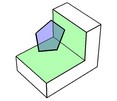
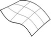
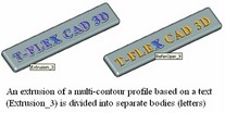
3D profile is a construction entity used for defining a patch on a surface. A 3D profile is one of the basic entities because it is used as an original reference for many operations. A 3D profile may be defined by an open or closed contour. A closed contour defines a fixed area on the surface that can be used as a base for various operations creating solid bodies. An open profile can be used as a base for creating sheet bodies only as it consists of wire geometry. There are many ways of creating a 3D profile. Thus, it can be drawn on a workplane, or get anew by a variety of modifications to an existing profile, and so on. One 3D profile may contain several contours of the same type. An example of a multi-contour profile is a text entity. A 3D profile can be obtained from hatches and graphic lines (when drawn on the active workplane). |
|
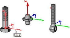
Local Coordinate System is an entity for referencing three-dimensional objects in space. It is used for inserting 3D fragments and other elements, copying, exploding of assemblies, etc. This entity is defined by the origin point and the axis directions. Objects snap to a coordinate system by making the object and the target coordinate systems coincide. |
|
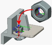
3D connector – is a special type of local coordinate systems which allows a user, apart from performing the functions of snapping, to automatically tie external variables for jointed parametric elements of the 3D assembly models. This significantly simplifies positioning of parts and parameters assignment when designing the assemblies. |
|
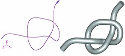
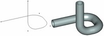
3D Path is a bounded three-dimensional curve with a defined traversal direction. The 3D paths are used in the operations "Sweep", "Pipe", "Loft". A 3D path can be defined by a hatch, 2D paths, as a chain of a body edges, as a curve passing through a sequence of 3D nodes, by modifying existing 3D paths, etc. A 3D path can be closed. |
|
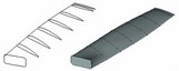
Pipe Path is a 3D path consisting of straight line segments smoothly connected by arcs. This command is mainly used for modeling pipes. A large variety of options and controls provided by this command help quickly and easily solving this sort of tasks. |
|
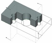
3D Section is an entity that, generally, results from extruding a planar curve or polyline through all geometry in the direction normal to the plane of the curve. In some cases, a 3D section consists of one or several planes. In this case, it can be used for creating two-dimensional cuts. A 3D section may be included in visualization of the objects of a 3D scene, and can be used in "cut" operations. |
|
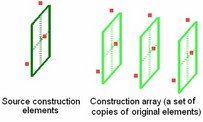
Construction array is a special composite construction element. A construction array is a particularly organized set of copies of an arbitrary construction element, except for sections, light sources and cameras. The copies contributing to such an array can be used as conventional construction elements. Construction arrays are created and edited using any of the 3D array creation operations. |
|
Basic three-dimensional operations
Extrusion yields a body formed by straight propagation of a contour along a specified direction. This operation creates both solid and sheet bodies. Extrusion can be performed along not only the extrusion vector, but the normal to the contour in either or both directions as well. Thus, it provides a means of thickening an arbitrary face, even a non-planar one. |
|
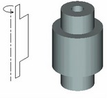
Rotation yields a body formed by revolving a contour around an axis located in space for a given angle. The original contour can be located in an arbitrary orientation with respect to the axis, but it should not intersect with the axis. This operation creates both solid and sheet bodies. |
|
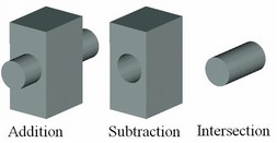
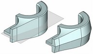
Boolean operation is intended for creating a new body by combining two existing bodies. The type of the operation is specified as addition, subtraction, or intersection. |
|
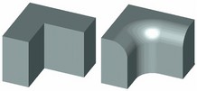
Blend Edge is an operation that modifies an existing body by smoothing or merging its vertices, edges and faces. The main difference of this operation from other types of blending is in that the new surface is created from the selected edge and merges with the adjacent faces only. The operation permits creating chamfers, edge rounding with a variable radius and elliptic rounding. |
|
Blend Face-Face is an operation for creating smooth transitions from one set of smoothly connected faces to another. The sets of faces to be blended may not have common edges (intersect). The command has numerous options for controlling the blending surface shape, trimming conditions, bounds, etc. This operation should not be considered a substitute for blending edges. Each of the two approaches has their own advantages and well complement each other. |
|
Blend Three-Faces is a special case of face–face blending separated into another command. The operation creates a transitional surface between a "right" and a "left" wall while tangent to a "middle" wall. |
|
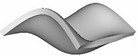
Loft is an operation for creating new bodies of complex geometrical shapes. The resulting spline surfaces are constructed on the wire guides in one or two directions and according to the specified boundary conditions. The base elements for spline definition can be practically any entities of the three geometrical types, "point", "wire" and "sheet". Depending on the base element type, the result will be either a solid body or a set of surfaces. |
|
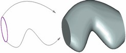
Sweep is an operation that creates bodies whose surface is defined by an arbitrary-shape profile propagated along a space curve. The operation provides controls over scaling of the profile and its twisting with respect to the trajectory axis as it moves along. |
|
By Parameters – this operation extends the capabilities of the "Sweep" operation. The base profile is defined in such a way that its geometry and orientation are driven by a variable. The driving variable can assume values within the specified range. The body is created as a result of recomputing the geometric shape and orientation of the profile across the whole range of the variable values. |
|
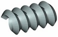
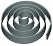
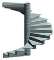
Spiral is an operation for creating spiral-like bodies. The generatrix contour can be defined by an arbitrary-shape profile. This operation may be used for modeling actual geometry of a thread. However, in most cases, when only cosmetic representation of a thread is needed, the "Thread" operation is recommended for use instead. |
|
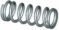
Spring is a specialized operation for creating spring-shape bodies. It differs from the "Spiral" operation in the capability of forming the end cycles of the spring. The generatrix of a spring is defined as a circle. |
|
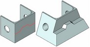
Cut is an operation that divides a body in two, or cuts a portion off a body. The cutting surface can be defined as a set of connected faces, or sections, or workplanes. |
|
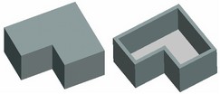
Shell is an operation that removes the inside material of a part by removing the selected faces and leaving the rest of the faces just thickened by the specified width in the direction where the material used to be, removing all the rest of the material. A shell can also be created without removing any faces. Another special functionality allows creating new bodies offset from a given one. |
|
Face taper is an operation that tilts selected faces at the specified angle while automatically adjusting other affected faces. |
|
Body taper is an operation that creates 3D bodies by tapering faces of a selected body at a specified angle with respect to selected edges of that body in the taper direction. This operation significantly simplifies the design of cast molds. Unlike "Face Taper" command, this operation allows creating two-sided tapers and tapered body faces without having a clearly defined "fixed" edge. |
|
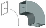
Pipe operation makes a pipe along a space trajectory (a 3D path). The user specifies the diameter of the pipe and the diameter of the outlet. The outlet itself is optional. |
|
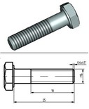
Hole is an operation for creating standard apertures. It relies on a provided parametric library of holes satisfying current standards. The command supports creation of patterns of holes, holes through multiple bodies, and threaded holes. When a threaded hole is created on a face, a cosmetic thread is displayed. |
|
Thread is an operation for creating cosmetic representation (imitation) of threads on cylindrical and conical faces of a 3D model. When the projections of the model are created on a drawing, the thread is automatically drawn according to drawing conventions |
|
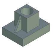
Rib – operation that allows us to create ribs of the solid body on the basis of one or several 3D profiles. Execution of this operation results in a solid body obtained via a Boolean operation of a union of the rib being created with the source body. |
|
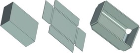
Sheet Metal Operations
The specialized sheet metal operations make a separate group.
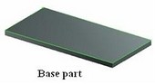
Create Part operation creates a solid body – a flat part. The base element for the operation is a flat closed 3D profile. The body is created by thickening the profile by a specified amount. The part material will be added along the normal direction to the profile at either or both sides of the profile. |
|
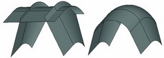
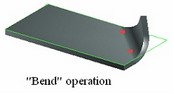
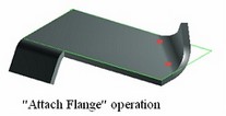
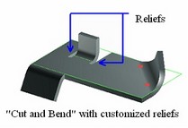
Bend operation supports three types of bending, "Bend", "Attach Flange", "Cut and Bend". ●The first type is for bending an existing body, such as a part, around an infinite axis defined by a pair of 3D nodes or a straight-line entity. ●The second type supports attaching a flange to the part according to specified length, width, bending radius and the offsets from the ends of the bending axis. ●The third type is for bending a portion of the part around a finite line segment. This is done by making appropriate cuts in the original body. The operation allows introducing reliefs defined by their type, depth and width. |
|
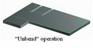
Unbend operation can be used after a sheet metal model has been defined, to get the flat part and proceed, for instance, with its drawing. Re-bend operation repeats bending of all surfaces that were previously "unbent". It provides a means of keeping the final bent shape with the model data. This is important, for instance, when creating a drawing with both the flat part views and a final bent shape view. |
|
Convert Solid to Sheet Metal. Command is used for quick creation of sheet metal bodies or unfoldings from the solid bodies. |
|
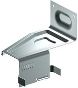
Forming Feature operation is specifically provided for performing common sheet metal stamping manipulations. It uses a library of typical elements for creating ribs, beads, flanges, embossings, louvers, etc. The geometry of these features is defined by 3D profiles. |
|
Face handling operations
The set of commands for direct handling of body faces are united into a separate group.
Sew is an operation for creating solid bodies or sheet models from a set of disjoint surfaces adjacent to each other, as faces, 3D profiles, sheet bodies. When sewing into a solid body, the operation may add simple surfaces as necessary. |
|
Imprint elements is an operation that forms patches of a specified shape on already existing faces. Depending on the dividing option, the shape of the new patch is determined either by the shape of the dividing element or by the geometry of the element being divided. |
|
Delete faces is an operation that allows deleting one or several selected faces. Deleting faces breaks the solid body topology. Gaps are introduced that invalidate the closed volume. If necessary, the system may attend to mend those by various means. |
|
Separate faces is the command for excluding selected faces from an already existing body and using those for creating a new body. The gaps in bodies caused by this process can be closed by one of several means. |
|
Replace faces is the command for substituting a geometrical surface underlying the selected faces by different surfaces. Sheet bodies can be used as a replacement surface. |
|
Change faces is the command for modifying face parameters when the underlying surface is analytical (a cylinder, cone, sphere or torus), as well as parameters of faces created by the blend operation. |
|
Transform faces is the command that applies a transformation to one or multiple selected faces. |
|
Expand faces is the command for expanding the selected face (or multiple faces belonging to a sheet body) in the specified direction by the given length. The direction of growing the face is defined by selecting side edges on the faces being expanded. 3D profiles can also be expanded. |
|
Fill hole is the command for creating one or multiple faces closing an area bounded by a closed loop of edges. Depending on the initial geometry, the system may fill the area by an analytical or a ruled surface, or by an explicitly specified sheet body. |
|
Copy and Insert Operations for 3D elements
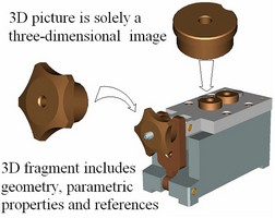
Insert 3D Fragment is an operation for using the geometrical data of a standalone 3D model in creating an assembly model. Any T-FLEX CAD document containing a 3D model can be used as a 3D fragment. Insert 3D Picture is similar to inserting a 3D fragment, except that the 3D picture has neither associativity among elements nor parametric modification capabilities. It is merely a shaded 3D image of a part that appears exactly as a 3D fragment. 3D pictures are handy at a final stage of design when the element modifications are no longer expected. Since 3D pictures are not subject to regeneration, the overall model regeneration time is reduced. 3D pictures cannot be used as references for other elements. Thus, faces of such objects can't be selected, and projections cannot be constructed. |
|
Copy is an operation for creating a transformed copy of a body defined by various transformation parameters. Copy operation utilizes a "local coordinate system" entity. |
|
Symmetry is an operation for creating new bodies as copies of the original of bodies by reflection at a specified symmetry plane. |
|
Divide is an operation for separating numerous bodies obtained from various operations. The resulting bodies can further be processed separately. For instance, the bodies created by an "Array" operation, will be separated into standalone elements. This command can also be used with an imported from other systems model that consists from several bodies. |
|
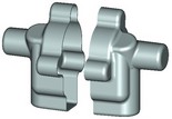
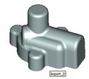
External Model is an operation for importing models created in other systems based on Parasolid format (*.x_t and *.xmt_txt). Just like 3D pictures, these objects do not possess parametric properties, however, their elements (vertices, edges, and faces) can be used as references for further design. |
|
Operations for creating 3D arrays
The array creating operations allow simultaneously creating multiple copies of source 3D objects. The source objects for creating arrays (objects for copying) can be not only operations and Bodies, but also 3D construction elements and faces.
Placement of the copies being created (the array elements) depends on the array type: linear, circular, array by points, array by path, parametric array.
Linear array is the one in which the copies of the source objects are placed along one or two direction vectors at a specified step. The copies can be placed not only in the forward, but also in the reverse direction along each direction vector. |
|
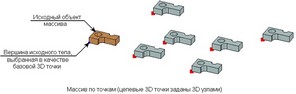
Array by points is the one in which the positions of the arrayed copies are defined by 3D points. |
|
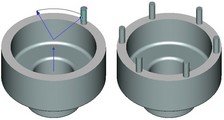
Circular array is the one in which the copies are placed on a circle around the array axis. Reverse rotation is also possible, including creation of copies simultaneously in two rotation directions. It is also possible to create copies in a second direction - either along the array axis or in the radial direction. |
|
Array by path is the one in which copies are placed along one or two spatial curves. One can set different ways of orienting copies on each guide curve – by the cord, by the minimal twist, by parallel translation. |
|
Parametric array is the one in which the spatial positioning and parameters of copies are defined by a specified parametric law. |
|
Array of construction elements makes copies of any 3D construction objects, except for sections, light sources and cameras. It results in a special 3D construction element – a construction array. |
|
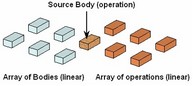
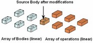
Array of operations copies only the result of the selected operation. If the body created by the operation is later transformed by another modifying operation, the array is not affected. Array of Bodies copies a whole Body. If that Body is modified in the future, the array will regenerate, accounting for the new operations added in the Body's history. |
|
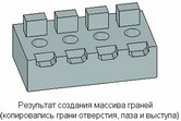
Array of faces is used for adding holes and protrusions repeating existing design elements, to Bodies already existing in the 3D model. Any array of faces is always based on one model Body: all copied faces must belong to this Body. |
|
Depending on the type of the copied objects, distinguished are the following array types: arrays of construction elements, arrays of operations, arrays of Bodies and arrays of faces. All arrays of one element type, regardless of their properties, share the specifics of creating and editing.
Deformation Operations
The operations of deformation allow a user to carry out modification of solid and sheet bodies by various means. When applying these operations on the basis of parameters specified by a user, an internal function producing the volume deformation of the deformed body is generated in the model. Applying this function in a continuous manner deforms the entire volume of this body (or its part). Topology of the deformed part of the body is not changed. The number of faces, edges, and vertices, etc. is preserved. If necessary, the faces and edges of analytical type (planes, segments, cylinders, arcs of circles, etc.) are automatically replaced with spline surfaces and curves.
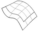
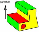
Skew – this type of deformation assumes existence of the original body and the coordinate system in which a bounding parallelepiped is calculated. Deformation law is specified by displacing the vertices of this parallelepiped in different directions. The displacement can be realized along any of the axes of the coordinate system, along the edges of the bounding parallelepiped, and along the diagonals of the faces of the bounding parallelepiped. |
|
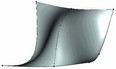
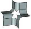
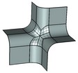
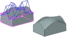
Sculpt deformation – in this type of deformation a regular mesh of points is defined on one of the faces of bounding parallelepiped. Any point on this mesh can be displaced relative to its initial position by a specified value. As a result, a flat face of virtual bounding parallelepiped is transformed into a space spline surface which forms the required transformation law for the body. The operation of sculpt deformation has 3 modes: ●One side – only the points located on one face of the parallelepiped are displaced; ●Both sides – the points located on opposite faces of the parallelepiped are displaced. The points on the face opposite to the selected one are displaced in the same direction by the same distance; ●Symmetric – points on the opposite face are displaced symmetrically with respect to symmetry plane of the parallelepiped. |
|
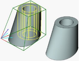
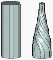
Scale/Twist – this operation allows a user to specify various scales and angles of twist in different sections along the axis of the selected coordinate system. This deformation can be carried out either for the entire body or within the borders of the user-defined region. In addition to scaling and twisting sections, it is possible to entirely stretch or compress the deformation region in the direction of the selected axis of the deformation. For sections, the scales along different axes can be different. |
|
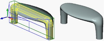
Bend – this operation allows a user to bend the selected body by a specified angle with respect to the selected axis. In addition to bending angle, the distance defining the location of the «neutral» surface is specified. |
|
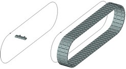
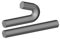
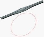
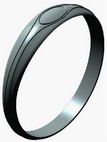
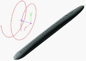
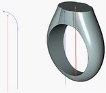
Deformation by curve – for the deformation by curve, the overlap of the source curve, associated with the deformed body, with the target curve takes place. The deformation function constructed as a result of this is applied to the deformed body. A user can control the location of the body with respect to the curve. Upon deformation, one of the three body orientation control algorithms and the ways of using the source curves can be chosen. ●D curve – 3D curve. This method uses one source and one target curve. In most of the cases in practice, the source curve is a line. As an example, consider one of the typical problems solved by the present algorithm – wrapping the source body into a ring. ●Curve – Spiral. The spiral-like curve is chosen to be a target one and the axis of the spiral is specified. ●Pair of curves – Pair of curves. The source pair of curves and the target pair of curves are specified. Additional curves perform the function of controlling the twist of the body with respect to the main curve. |
|
Deformation by surface – this type of deformation forms the transformation law of certain single surface into another surface and applies this law to the source body. As the initial data from the source and target sides, the surfaces and the three points on each surface are chosen for the subsequent overlap. An additional displacement of the resulting surface from the source surface can be also specified. This transformation works in two modes – «By parameters» and «With minimal distortion». In the former case, the exact overlap of the parametric surface spaces by the selected points is carried out. In the latter case, the proportions of the geometric distances measured between certain points on the source surface are preserved. |
|
Commands to create welds
A group of commands in the “Tools|Weld” menu is provided to design welded parts. Those serve to create various types of standard and nonstandard welds on a 2D drawing or in the 3D model. Once a weld is created, its symbol can be automatically applied, and tables of welds can be built.
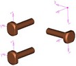
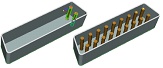
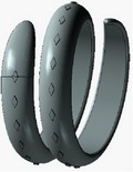
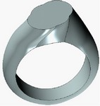
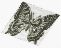
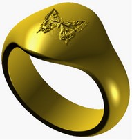
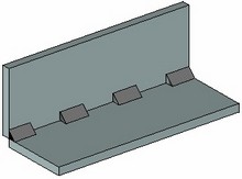
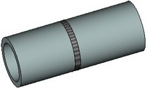
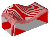
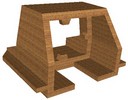
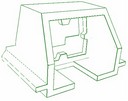
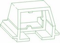
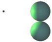
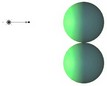
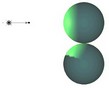
There are the following 3D weld types: fillet, intermittent fillet, butt, composite. Fillet, intermittent fillet, and butt 3D welds are denoted in the 3D scene with a special “cosmetic” body with a characteristic texture.
|
|
|
Fillet 3D weld |
Intermittent fillet 3D weld |
Butt 3D weld |
The composite weld is a variation of the 3D weld. It can be used to designate some 3D model elements (bodies, edges, 3D profiles, 3D paths, or a combination of several existing 3D welds) as a 3D weld. In this case, no image of the weld will be created in the 3D scene.
Geometry analysis commands
Measure is a command for defining mutual situation of objects on the 3D scene, whether one body penetrates another one, what is the minimum distance between elements. Besides that, various geometric characteristics can be computed for selected elements, such as length of an edge, area of a face, coordinates of nodes, etc. One can introduce variables that will be gaining specified characteristics from the elements of interest, using special functions. Thus, these characteristic values can be used as input for further construction.
Mass-Inertia Properties is the command for calculating the mass-inertia properties of the selected operations. If necessary, the calculations can be done with respect to a specific coordinate system.
Model check is the command for diagnosing the selected body for errors in its geometry.
Intersection Check is the command for examining the model against intersections and contacts between selected bodies. The command is particularly helpful when working with assemblies. |
|
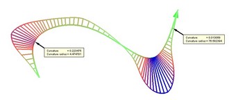
Curve curvature is the command for measuring the curvature and the radius of curvature on selected curves. The curvature is displayed in the form of the porcupine quill. To measure curvature, you can select edges and 3D paths. |
|
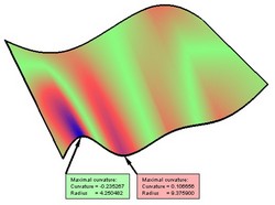
Surface curvature is the command for measuring curvature and the radius of curvature of one or multiple selected faces. You can watch the overall curvature distribution on the face (the model is colored appropriately for this purpose), or read the curvature value at a specific point. |
|
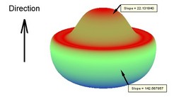
Surface deviation is the command for defining the selected face's normal deviation from the specified direction. The colored face display allows watching the deviation all over the face. You can also measure the deviation at a specific point. |
|
Surface gap is the command for evaluating the gap between two or multiple selected faces. The command is used for analyzing models suffering import/export deficiencies. |
|
Normal deviation is the command for measuring deviation between the normals of the neighboring faces evaluated on the specified edges. The quills displayed in the 3D window help watching normal deviation across the overall edge extend. Besides that, the angle of the normal deviation can be measured at a specific point. |
|
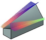
Surface smoothness is the command for evaluating the model regularity. On entering the command, a special pattern is applied to the body's faces, usually made by long light and dark stripes. This pattern helps usually determine whether the adjoining faces make a smooth tangency transition, or smooth curvature transition. |
|
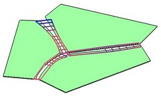
Model Separation Check is the command for identifying faces of the areas preventing a die cast or injection mold from opening. Additionally, the faces are highlighted, whose slant angle with respect to the selected direction is less than specified. |
|
Engineering Analysis
Besides the geometry analysis commands described in the previous paragraph, the T-FLEX CAD complex provides additional modules serving to conduct advanced model analysis: Finite Element Analysis and Dynamic Motion Analysis.
Finite Element Analysis – this is a “T-FLEX Analysis” module that serves to perform various types of finite element calculations:
●Static analysis allows calculating the state of stresses and strains in a structure under the impact of constant in time forces applied to the model;
●Frequency analysis allows calculating natural (resonant) frequencies of a structure and the respective vibration modes;
●Buckling analysis is important when designing structures, whose operation implies lasting influence of loads ranging in intensity;
●Thermal analysis is the module providing the capability of evaluating a heated product behavior under the impact of sources of heat and radiation.
T-FLEX Analysis is oriented at solving physical problems in the three-dimensional formulation. All calculations rely on the finite element method (FEM). The product's mathematical approximation uses its equivalent replacement by a mesh of tetrahedral elements. At the same time, an associative relationship is maintained between the three-dimensional model of a part and the finite element model used in the calculations. Parametric modifications of the original solid model are automatically propagated into the meshed finite element model.
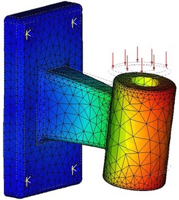
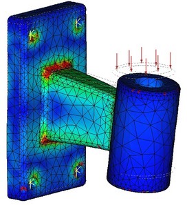
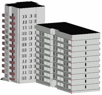
Results of finite element modeling (displacements and stresses)
The standard T-FLEX CAD 3D distribution kit includes only a limited trial version of the finite element analysis module – Express Analysis. The Express Analysis is a light version of the “T-FLEX Analysis” module, specifically tuned for running simplified yet qualitatively sound strength studies. The user is provided with the necessary selection of load and restrained types. Based on the T-FLEX CAD model geometry, the automatic mesh generator creates a quality finite element discretization within the Express Analysis. Once the calculations are completed, the stress, strain, displacement and strength safety factor are output in a graphic form.
The fully functional “T-FLEX Analysis” finite element analysis module is sold separately.
For details on working with the finite element analysis module, please refer to the “T-FLEX Analysis” manual.
Dynamic Motion Analysis – this is the module that serves to run studies on dynamic behavior of various three-dimensional mechanical systems.
The dynamical analysis module is capable of solving the following studies:
●Analysis of the motion trajectory, velocity and acceleration of any point of a component in a mechanical system due to applied forces;
●Analysis of performance times of a mechanical system (the time to the target point, the time for vibrations to settle, etc.);
●Analysis of forces building up in components of a mechanical system during motion (reaction forces at the supports, joints, etc.).
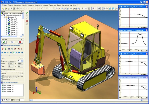
A mechanism's model is defined as a system of solid bodies, joints, and loads. The data for the analysis is automatically accessed directly from the geometrical model created in the T-FLEX CAD system. The familiar tools of T-FLEX CAD are used in modeling, with mates and degrees of freedom employed to define relations between three-dimensional bodies. The system also provides the means of modeling the contact between arbitrary solid bodies, being capable of processing a simultaneous contact of hundreds and thousands of solid bodies of arbitrary shape.
Loads on solid bodies are defined as the initial linear and angular velocities, forces, moments, springs, gravity, etc. To read the results, special sampling elements are used. Numerous values are available for the analysis: coordinates, velocities, accelerations, reaction forces in joints, forces in springs, etc. The user can observe the model behavior from any viewpoint immediately during the actual calculation. One can create animation clips from the obtained results of a dynamic calculation.
The T-FLEX CAD 3D standard distribution kit includes only a limited trial version of the dynamic analysis module – the Express Dynamic Analysis. The Express Analysis has certain limitations on load types and the ways of rendering dynamic analysis results (the tools to obtain numerical calculation results are not available). In the commercial module, the calculation results are displayed as graphs, dynamic vector arrows and as an array of numbers (graph points).
The fully functional dynamic analysis module can be purchased separately whenever needed.
More details on working with the dynamic analysis module are provided in the “T-FLEX Dynamic Analysis” manual.
Auxiliary Elements and Operations
Material is a system element assigned as a parameter to each created body. Material helps rendering computer models so that they look like real objects. It contains a list of characteristics of the real material used in actual production. Material has the following parameters: density, luminosity, ambience, etc. The whole body material can be assigned within parameters of any operation.
Apply Material is an operation that assigns a material to specific faces of a body.
Transformation is a command for defining translation and rotation of an object that change its location and orientation on the 3D scene. This command works with all operations and most 3D construction entities.
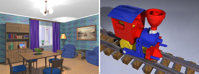
Photorealistic Imaging is a command for creating a file in BMP format containing a photorealistic image of the objects on the 3D scene. This is done with POV-RAY application that is shipped together with T-FLEX CAD 3D. Photorealistic images are also used for creating animated clips.
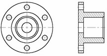
2D Projection
2D Projection projects all bodies of three-dimensional scene or selected bodies or specified elements on a plane. The resulting image is displayed in 2D window. Projection creation accounts for sections for instance when creating cuts. This approach helps avoiding additional constructions in 2D window. Simply create a three-dimensional body, and all necessary views in 2D window will be obtained by projection. Further, 2D projections can be used for laying out drawings.
3D Annotation
T-FLEX CAD allows creating drawing annotation (dimensions, leader notes, roughness symbols) directly on faces, edges and vertices of a 3D model (see chapter "3D Annotations").
The capability of creating 3D annotation allows introducing in a 3D model not only geometrical, but also technological process and other information that can later be used when creating drawings by 2D projections, as well as in other applications, for example, in the process design modules or when creating CNC control sequences.
3D Object Rendering
View is a combination of 3D window parameters, such as view point, distance to object, visualization parameters, the type of projection, etc. Particular sets of these settings can be saved in order to quickly set up 3D scene in required configuration later.
Rendering type is a way of rendering 3D bodies in the 3D window.
First type is Wireframe model. This way is convenient in that the front elements do not obstruct the ones behind, and the objects inside the body can be seen as well.
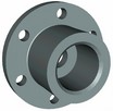
Second type is Shading. The faces of the bodies are displayed in a specified color.
Third type is Shading with Material. The faces display accounts for the material specified for the whole body, as well as applied to particular faces.
Fourth type is wireframe with Hidden line removal. A fast algorithm is used for determining line visibility.
Fifth type is wireframe with Precise hidden line removal. The wireframe is displayed with invisible lines removed per the current orientation.
Projection method defines the way objects are represented on the 3D scene. It may be parallel projection without perspective that does not account for the distance from eye to object and the perspective angle, or projection with perspective that does account for the above parameters.
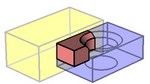
Clip plane is a plane situated parallel to the screen when originally defined. It can move back and forth along the fixed direction and clip out the portion of the objects on the scene before the plane (to move Clip plane use: ![]() +Ctrl+Shift). It is used for visual analysis of inner elements of the bodies, and for selecting objects on the 3D scene located inside the bodies.
+Ctrl+Shift). It is used for visual analysis of inner elements of the bodies, and for selecting objects on the 3D scene located inside the bodies.
Light Source is an element for controlling the illumination of the 3D scene. Originally, there is a single light source coinciding with the viewing point. A light source can be a Spot Light, a Direction Light, and a Projector. The user can create additional lights as needed, vary their intensity and direction, turn on or turn off any of them. Light source is used for creating a photorealistic image.
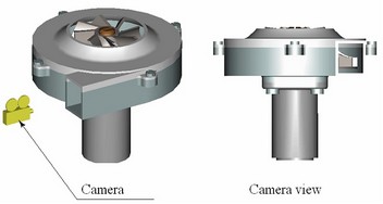
Camera is an element that defines the viewing point and direction on the 3D scene. Each 3D window has one default camera. One can create additional cameras, select an active camera. The newly created cameras can be moved using special cursor or bounded to a local coordinate system. The viewing direction of a camera can also be changed. This helps surveying inner elements of the scene and create animated clips.
Three-Dimensional Model Animation
Animation of a three-dimensional model is done by the same means as drawing animation, that is the variable-driven model modification. The user assigns the range and the step for the variable modification. Since the real-time regeneration of a three-dimensional model driven by a variable modification may be slow, the animation may not look well in interactive session. This is why a good strategy is to create a multimedia file in *.AVI format (a video clip) for watching the modification animated.
A video clip may be created using photorealistic imaging. In this case, each frame of the clip will be processed by the POV-RAY application.