Approaching Solid Modeling with T-FLEX CAD 3D


Approaching Solid Modeling with T-FLEX CAD 3D |
|
General recommendations before you begin with 3D model creation
Analyze the design intent before starting 3D model creation. The degree of design automation depends on how well the engineer thought through of the model layout. Parametric design requires additional time investment at the initial stage as compared to non-parametric approaches. However, this brings an unmatched advantage at the later stages, as, for instance, in preparing documentation for various modifications of a product.
Due to high flexibility of the system, the same result can be achieved by different means. One of the foremost goals of the designer is to find an optimum solution. Naturally, this depends on how well the designer manages to operate the instruments provided by T-FLEX CAD 3D system.
First, decide what operations you will use for creating the elements of a part. Important is what kind of references and interdependencies will be imposed on various elements. Define the appropriate boundary conditions. Determine what model parameters should be represented by variables. Divide a complex assembly into a set of fragments, 3D pictures, copies, and library elements. Begin with a model creation after realizing a rough plan of the design layout.
Parameterization and Model Regeneration
A T-FLEX CAD model is constructed as follows. First, create a new Body using 3D operations based on construction and other auxiliary 3D elements. Next, a base body is used to create other Bodies, which, in turn, undergo modifications and alterations, become subject to certain dependencies, boundary conditions, and so on. Each construction element or operation is recorded in the model history. It is possible to identify parent-child relations between certain elements. The model hierarchy is represented by a tree structure.

Now, suppose, some parameter of a parent element operation needs to be modified that would affect its geometrical configuration. This would cause the children to adjust their locations according to the parent geometry and the model parametric dependencies. T-FLEX CAD is capable of handling such issues due to its architecture that supports through-model parameterization.
The word "parameterization" implies a wide range of capabilities. It is possible to modify virtually any parameter of any operation at any time. Besides, parameters are not limited to numerical or textual values, as they also can be represented by variables. The variables can be driven by certain expressions, and be dependent on other parameters and variables.

Again, suppose, we changed a parameter of a parent element. Next, the model regeneration is launched manually or automatically, traversing the model structure and recalculating the model with the updated variable values.

T-FLEX CAD supports full and partial regeneration. Full regeneration is necessary for updating the whole drawing and the model. This causes recalculation of all objects from scratch. Partial regeneration saves time. The system automatically analyzes what objects were modified since the last regeneration, and recalculates these objects and their children only.
To update a model use a selective regeneration command,
Icon |
Ribbon |
|---|---|
|
Parameters → Tools → Regenerate |
Keyboard |
Textual Menu |
<Alt><F7> or <3G> |
Tools > Regenerate |
The full regeneration is invoked by the following command,
Icon |
Ribbon |
|---|---|
|
Parameters → Tools → Full Regeneration |
Keyboard |
Textual Menu |
<3RG> |
Tools > Full Regeneration |
The three-dimensional model is fully regenerated after calling the command. This command regenerates each element, unlike the Regenerate command, which regenerates only changed and dependent elements. The image in 3D view window is automatically updated after the regeneration.
The following window appears after calling the command:


If the flag Regenerate drawing 2D projections is set, only changed 3D elements (optimal regeneration) and all projections will be regenerated.
If the flag Regenerate other 3D elements is set, all 3D objects are regenerated.
If you set both flags, the full regeneration is performed. If both flags are not set, the optimal regeneration is performed.
The flag Update links allows to update files used in the current document (fragments, images, data bases). You can set to update Changed only links or All links. The command UL: Update links is indirectly performed in this case.
The flag Update product structures allows to update all product structures created in the document.
The flag Update reports/bills of materials updates all reports and bills of materials created in the document.
When you set Don’t ask this question again this window will not appear next time after calling the command.
Three-Dimensional Model Creation Techniques
T-FLEX CAD supports various techniques of 3D model creation. The mainstream design principle implies direct approach to a 3D model creation "from scratch to workplane to sketch to model". Another approach implies use of pre-designed 2D drawings or auxiliary 2D construction. This technique can be called "from 2D to 3D model".
Whichever technique is used in a 3D model creation, the same operations form the body geometry. The difference is in the ways of creating the 3D construction entities.
The Mainstream Approach.
Charted below is the mainstream design approach workflow.
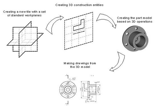
Begin a document creation by selecting an appropriate prototype of a 3D model (3D model.GRB). Use the command "F3: File|New 3D Model". This brings up a 3D window with a standard set of workplanes. Now all is set for starting with a 3D model.
The mainstream 3D modeling approach does not require the 2D window. All auxiliary elements, including profiles, nodes, 3D paths, etc., can be constructed directly in the 3D window using the same 2D drawing tools.
Normally, an operation requires a certain set of auxiliary 3D construction entities to be completed. To create a 3D profile, first select a workplane or a flat face as a base, then all 2D drawing commands become accessible. Just like in 2D, one can draw on the active workplane new lines, contours, etc. Parametric dependencies can be automatically introduced into the model at this early stage. A 3D operation, such as, say, an extrusion, can be invoked without leaving the drawing mode. The system would automatically create a 3D profile based on the just created graphic lines. This minimizes the number of user actions required for completing an operation. Consider, for instance, the "Rotation" operation. The required axis (a dashed line) and the contour can be created on the fly directly on the workplane. Preview is always available to evaluate the result of an operation. Preview activates automatically for the operations that do not require extended time for computations. In other operations, it is invoked by a special command.
The bodies created at an early design stage may later be used in other operations, such as in Booleans, blends, tapers, etc.
The completed 3D model can be used for generating drawings, if desired. Create required projections, sections and cuts that can be used as references for the necessary elements of the drawing layout, dimensions, etc.
"From 2D to 3D" Technique
The following chart illustrates a design technique "From 2D to 3D".
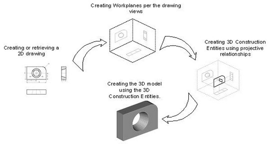
Often, a 2D drawing of a part may already be available before beginning with the 3D model creation. The proposed approach to model creation is preferable in such a case. At the initial stage, it is good to have a 2D drawing of the part that contains all necessary views. The part views are better be laid out in accordance with the projection rules, although this is not a strict requirement. Certain parametric relationships of the pursued parametric 3D model can be introduced at the 2D drawing stage. The first step in 3D model design is creation of workplanes. Often, two or three orthogonal workplane are sufficient that represent the front view (the front plane), the top view (the horizontal plane), and the view from left (the side plane).
Next, the necessary 3D construction entities are introduced, such as 3D nodes and 3D profiles. 3D nodes are used as references for 3D profiles, vectors of extrusion direction, rotation axes, etc. In case a workplane can't be activated, the required profile can be defined based on a 2D hatch. The hatch must reference an actual drawing.
Besides the profiles, 2D views can be used for constructing 3D nodes from the 2D nodes, and 3D paths from the 2D paths and other construction entities.
It is thinkable of combining the two techniques described above. Note that three-dimensional modeling is a creative process that does not necessarily implies a sole way towards a particular solution. The user is provided the necessary set of tools, while it is up to him to make a choice of a most effective approach to realizing the design intent.
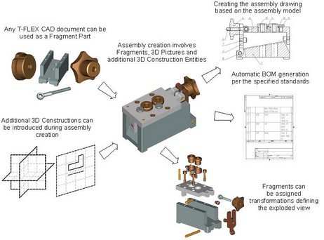
Creating Assemblies
Any T-FLEX CAD 3D document that contains a three-dimensional model can be inserted into another 3D model as a fragment. Thus composed model is called assembly. External models, imported from other systems in an appropriate format, can also be used in assemblies.
The component architecture of T-FLEX CAD assemblies has certain advantages. Thus, one can create libraries of parametric elements, to use them later in assembly creation.
An assembly document keeps the references to the fragment files. Once a fragment file is modified, it automatically becomes updated, causing modification of the respective assembly component. Any fragment may have external variables that drive the parametric relationships of the part. At any time, one can either modify the original part file of the fragment, or specify different values of the external parameters of the fragment. In the latter case, the part file is unchanged, while the assembly component – the fragment – is recalculated per the new external parameter values. A special functionality helps keeping various sets of the assembly parameter values thus facilitating quick loading of a desired variation.
Each fragment file provides storage for BOM data. If this data is entered in each fragment file then the assembly BOM can be output automatically.
The assembly model can be used for creating drawings by creating the necessary views, cuts, sections and applying dimensions and other layout elements.
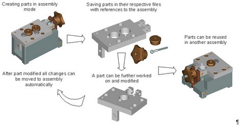
"Top-down" Assembly Modeling
There is an alternative approach to assembly creation, as opposed to the typical one briefly described above. T-FLEX CAD supports new part creation based on any geometrical and topological elements of the parent assembly. In this way, it is no longer necessary to specify placement conditions and the part mutual configuration. A part is automatically placed according to the references to elements used in the part definition. The parametric relationships among the assembly elements are saved with the model. Once a dimension or a part placement is modified, all related elements of the assembly will automatically adjust.
When working with a part in assembly mode, all elements that are not referenced by the part are shown transparent. Snapping works with all assembly elements. Any assembly element may be referenced at any moment.
The part is saved in a separate file. The file may be opened apart from the assembly and worked on separately. The assembly references are meanwhile preserved.
3D Model Rollback Mode
If you need to make a correction to an already created model, you can use the 3D model rollback mode at a certain operation level. This function is helpful in the cases when you need to do additional work in the middle of the model tree.
In the rollback mode, the 3D model returns to an earlier stage of its creation. Elements and operations that follow after the rollback point in the model's history become hidden in the rollback mode and are inaccessible for selection. In this state, those are marked with semitransparent icons.
All elements and operations created in the rollback mode are automatically inserted in the 3D model tree between the operation, upto which the rollback was made, with the successive operations unloaded from the scene. It is possible to do a series of rollbacks.
Upon finishing the rollback mode, the system automatically rebuilds internal model relations to restore the later operations. If for some reason the introduced changes result in errors in the model, then the system will offer restoring the model state before the rollback. This protects the user from introducing invalid modifications to the model.
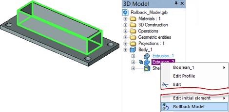
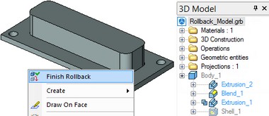
The rollback mode is invoked and finished using context menu commands of an operation in the model tree or in the 3D view window. The rollback will be up to the level of the operation, from whose context menu the command was called.
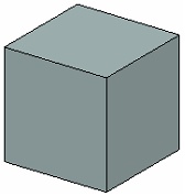
Let's review the use of a rollback on a simple example. In this model, it is necessary to add a blending on corner edges.
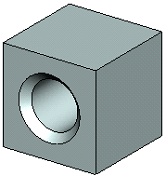
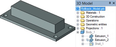
We perform the model rollback up to the base extrusion operation. In this case, the operation Shell_1 is unloaded from the scene.
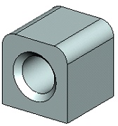
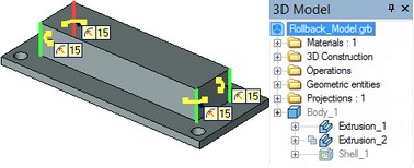
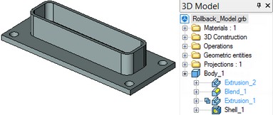
Then we make an edge blending (the Blend_1 operation is added in the model tree).
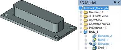
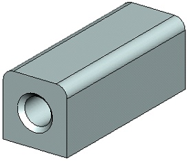
We then finish the rollback.
As a result, we get the model presented at the following figure.
Indicators of 3D Model Graphical Representation
When working with 3D models you can monitor parameters of graphical representation. To do this, set " Display graphics performance data" flag in "SO: Set System Options" command ("3D/Graphics Settings ..." tab). When flag is checked the upper left corner of 3D view will display the following information:
●FPS - number of frames per second;
●Batch - number of switching buffers when loading bodies into a 3D scene. This parameter depends on the number of bodies in the scene.
●Vertex - number of vertices in the scene. Vertex in this case refers to a set of vertex data (coordinates, normals, texture coordinates, and other vertex data).
●Face - number of triangular flat faces in the mesh;
●Line - number of lines in the scene;
●Point - Number of points.
●MTr/s - speed of mesh triangles drawing. Measured in millions of triangles per second.
To improve performance, you should seek the ways of reducing the quantitative graphical representation of models. You can control this via the mesh quality parameters.