"Bottom-up" Design


"Bottom-up" Design |
|
When using the "Bottom-up" approach, the assembly model design starts from creation of separate assembly elements – fragments. A fragment drawing is originally created as a standalone T-FLEX CAD document. In the process of creation, it is necessary to follow the certain rules that will allow in future to "snap" the fragment to the elements of the assembly drawing.
A special mechanism is provided in T-FLEX CAD for correct positioning of the fragment drawings in the assembly - Fixing points or vectors. Such elements should be created in a fragment drawing in advance, before inserting it into an assembly drawing.
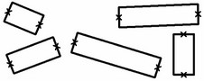
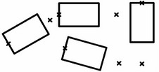
When inserting a fragment, you need to specify the position of the reference elements in the assembly drawing, which will define the fragment position, orientation and size. The fragment image will be built according to the specified fixing points or vectors. If no attachment elements are created in the fragment drawing, such fragment will be attached to the coordinate system of the assembly drawing page according to its initial coordinates in this page. The position of such fragment can be modified only by editing. To get associated relations between the fragments and the assembly drawing, attached fragments to the nodes of the assembly drawing (including the nodes of other fragments).
Ways of attaching fragments
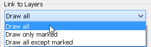
When designing assemblies by «Top-down» approach, two ways of positioning the fragment on the drawing are primarily used in the T-FLEX CAD system:
● Defining fixing vector. In this way, first create the drawing, and then define the necessary number of fixing vectors. Each fixing vector defines the origin and the positive direction of the X-axis of one local coordinate system in the drawing. An arbitrary number of fixing vectors can be defined within a fragment drawing. The fixing vector defines the fragment position and orientation one the assembly drawing and controls elements visibility.
● Defining fixing points using variables. In this way, the drawing is created first, following certain rules. The base vertical and horizontal lines are assigned the parameters with the reserved variable names. Upon assembling, the system will identify the intersection point of such lines as a fragment fixing point. Multiple fixing points are allowed. All the rest of fragment constructions are done with respect to the base lines defining the fixing points. The fixing points can define the position, orientation and size of the fragment within the assembly drawing.
The main difference between the fixing vector and fixing point approaches is in the sequence of creation steps of the fragment drawing. When using fixing vectors, you need to create the drawing first, and then specify the fixing vectors. When using the fixing points, one has to create fixing points first, and then build the drawing of the part based on the fixing points.
There are also differences in the uses of fixing vectors and points. Fragments with fixing vectors are created as follows: first, the image of the fragment is formed, taking into account the visibility layers. Next, the complete image is moved to the specified point and rotated by the specified angle without distortions. Fragments with fixing points are created differently: upon specifying the fixing points, all construction elements dependent on those points are rebuilt first, and then the image of the fragment is obtained.
This difference in forming the fragment image on the assembly drawing leads to differences that can be illustrated by the following example. Let's create identical fragments with different fixing provisions. Insert these fragments into a drawing, rotated by the same angle. The fragment that uses a fixing vector, exposes a change in the hatch angle, nonstandard dimension placement (with the automatic dimension text orienting functionality disabled), and a changed angle of a text. The fragment that uses fixing points shows the hatch angle preserved, the dimension "10" rotated per the standard, and the text angle maintained as well.
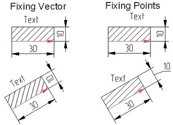
The mentioned differences shall not be considered shortcomings; rather, those are features that can be exploited in certain design situations.
Fixing vectors. Connectors
A fixing vector and a connector auxiliary elements of the model which are used when attaching the fragments. These construction elements are constantly displayed on the screen and can be hidden together with other construction elements by the command "Hide Construction". Context menu is available for those elements, providing the deletion, editing and property modification commands.
To use a fully furnished drawing as a fragment, one needs to create a fixing vector. To prepare the environment for fast "snapping" of other fragments, one needs to create a connector. The connector does not have to be created in the fragment drawing. It can be created in an assembly drawing.
Fixing vectors and connectors have different purpose, however, are created in the same command "FV: Construct Fixing Vector":
Icon |
Ribbon |
|---|---|
|
Draw → Insert → Fixing Vector |
Keyboard |
Textual Menu |
<FV> |
Construct > Fixing Vector |
Upon calling the command, the following options appear in the automenu:
![]() <F> Create Fixing Vector
<F> Create Fixing Vector
![]() <C> Create Connector
<C> Create Connector
![]() <A> Set Snap Elements
<A> Set Snap Elements
![]() <N> Select Node
<N> Select Node
![]() <F4> Execute Edit Fixing Vector Command
<F4> Execute Edit Fixing Vector Command
![]() <Esc> Exit command
<Esc> Exit command
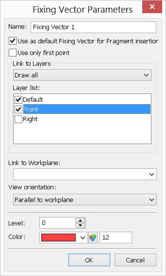
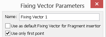
Fixing vector properties
There are two types of fixing vectors: a fixing vector defined by two points, and a fixing vector defined by one point. Fixing by one point is used for fast attachment of parts, whose image does not change under rotations, or parts not requiring rotation.
When creating a fixing vector, in its parameters specify the layers of the drawing to be displayed in the assembly. This allows, for example, inserting different views of the same part in an assembly.
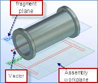
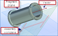
If the 3D model exists in the document, then the fixing vector can be bound to a specific workplane. This allows using 2D fragments in three-dimensional assemblies for defining the position of a three-dimensional fragment in the space with respect to the final position of the fixing vector and the selected workplane. This assembly creation technique is called "Layout". Detailed information on this technique can be found in the three-dimensional modeling manual, the chapter "3D Assemblies". This kind of relation allows inserting a 3D fragment automatically when the respective 2D fragment is assembled. To enable this feature, set the flag "Auto create 3D Fragment" in the command FR:Create Fragment.
Fixing Vector defined by two points
When inserting a fragment with such fixing vector, the position of the first point (the vector start) will be defining the fragment placement position within the assembly drawing, while the second point position (the vector end) - rotation of the fragment in the assembly. To create such vector, subsequently select two nodes by clicking Layer list. This pane contains the list of all layers existing in the drawing. Here you can mark those that will be displayed when assembling the document as a fragment using this particular fixing vector. |
|
On the diagram below, highligted are the fixing vector and the drawing elements to be carried over to the assembly drawing. Those elements are assigned a new layer. Exactly this layer must be check marked in the fixing vector parameters.
After that, when assembling these drawing as a fragment, only the check marked layer will be displayed in the assembly drawing, and, therefore, only the elements that lie in this layer will be displayed.
If a fixing vector has linked layers, its context menu will provide the command "Apply Layer visibility". Calling this command shows or hides the layers in the way in which they will be displayed when assembling the document as a fragment, using this fixing vector.
Link to Workplane. This parameter has a meaning only in the 3D version of the system. It servers for defining the workplane to which the given fixing vector will be bound. This functionality is used when creating layouts (see the chapter "3D Assemblies").
View orientation. View orientation is used when creating layouts (2D fragment on a workplane by 3D fragment). It allows us to select condition for which the schematic view will be added to the assembly’s plane. Only three options are possible:
●«Parallel to workplane» − after addition of the model to the assembly, the model’s schematic image will be created only under condition that the workplane of the assembly is parallel to the workplane in the file of the fragment with which the vector is linked.
●«Axial symmetry» − it is used for models of body of revolution type. After addition of the model to the assembly, the model’s schematic image can be created on any plane of the assembly which is parallel to a line on which the fixing vector is lying.
●«Arbitrary orientation» − it is used for bodies with central symmetry or having identical pseudo-graphical display of several views. After addition of the model to the assembly, the model’s schematic image can be created on any plane.
Fixing Vector defined by one point
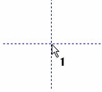
To create such fixing vector, select a node in the drawing by clicking |
|
When inserting a fragment, only one point will be asked. It won't be possible to define rotation for such fragment. If the flag "Use only first point" is not set, then a two-point fixing vector will be created. The direction of such fixing point will coincide with the X-axis of the fragment drawing.
To create a connector, upon calling the command "FV: Construct Fixing Vector", activate the automenu option:
![]() <C> Create Connector
<C> Create Connector
The system will then go into the mode of defining nodes. A connector can be defined by one or two nodes. If only one node needs to be specified, you can use the icon ![]() after selecting the first node.
after selecting the first node.
If a connector is defined by one node, then its drawing image will be a point. This leaves the only possibility of geometrical attachment to it of the fragments with the fixing vector defined by one point (only the origin, no direction). For easier fixing by such a connector, we recommend establishing the references between such connector and several drawing elements (see below).
If a connector is defined by two nodes, then, upon snapping to it a fragment with a two-point fixing vector, the fragment will be automatically positioned by bringing together the two vectors.
Upon specifying the nodes, the connector parameters dialog box automatically appears for defining the variables and the common properties of the connector. The connector variables are defined on a separate tab of the dialog box.
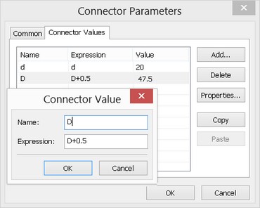
Initially, a new connector does not contain any variables. At the time of creation, the user normally already knows the purpose of creating this connector and, in particular, what parameters of the connector fragments to control with it. If, for example, we create a connector on the axis of a shaft, we will be connecting to it the fragments of parts to be mounted on the shaft. Therefore, we need to pass the shaft diameter value to the fragment being connected (say, a ball bearing).
To create a new variable in the connector, press the button [Add]. In the coming up window, define the name of the connector variable and its expression. The name of the connector variable should correspond with the name of the variable in the fragment to be mounted (in our example, it is a ball bearing and its variable driving the mounting diameter). In this case, the system will be able to automatically pass the value of the connector variable to the fragment being connected. The "expression" field allows entering a number (or text, in quotes, in the case of a text variable), and expression or a name of a variable belonging to the current document.
The name of the connector value is used subsequently upon attaching another fragment to the given connector. The name of the external variable of the fragment may not coincide with the value of the connector. At the moment of attaching the system uses a special parameter of the fragment external variable called «Connector values» (see the chapter «Variables» for details). If in the list of values of the external variable connector the name coinciding with the value stored in the connector, to which the fragment is being attached, will be found, then the value for the external variable will be automatically read from the connector. Link with the connector will be retained. Also, when attaching to the connector there is a possibility to manually link any fragment external variable directly with one of the connector values (see below «Specifying values of fragment external variables»).
The number (or the text in quotation marks for a text variable), expression or the name of the current document variable can be put into the field “Expression”. In our example, the value of the diameter, which is driven by a certain variable (for example, ‘D’) in the shaft model, has to be passed to other fragments. When creating the named value for the connector, it is possible to assign the name ‘Diameter’, and put the variable ‘D’ into the expression field. When creating the ball bearing model, in the properties for the variable driving the mounting diameter, it is necessary to specify the new value of the connector with the name ‘Diameter’.
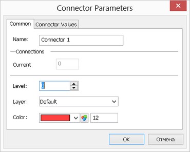
The tab "Common" allows defining basic properties of a connector as an auxiliary drawing object – name, level, layer and color. Besides, a special box in this tab tracks information about the number of connections to this connector (if the dialog of the connector properties is open directly in the assembly drawing).
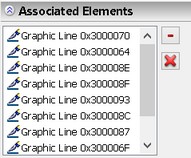
Defining associated elements for connector
To define associations of graphic lines with a connector use the option in the automenu:
![]() <A> Set Snap Elements
<A> Set Snap Elements
Upon selecting the option, the system enters the mode of selecting lines in the drawing that will activate the connector once pointed at by the mouse. To add elements to the connector, select those by the mouse in the drawing window. The selected elements are included into the list of associated elements in the properties window.
Insertion rules
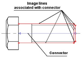
So-called «insertion rules» can be additionally defined for a connector. These are additional transformations of translation and rotation with respect to the coordinate axes of the connector which the system will prompt a user to carry out when attaching a fragment to a given connector. For example, when attaching a nut to the bolt connector, in practice it is always required to specify additional translation of the nut along the axis of the bolt. That is why when designing the bolt model, in the insertion rules for the bolt connector the necessity of translational motion along the X-axis of the connector has to be specified.
Fixing points
A fixing point is created as an intersection of a vertical and horizontal lines, whose parameters are defined by variables with reserved names.
The variables reserved for the vertical lines are: x1, x2, x3, x4, x5, x6, x7, x8, x9.
Those for the horizontal lines are: y1, y2, y3, y4, y5, y6, y7, y8, y9.
The numeric postfix of X and Y corresponds to the number of the fixing point and must match between the vertical and horizontal lines that define one fixing point. Up to nine fixing points are supported in a drawing.
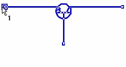
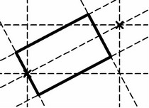
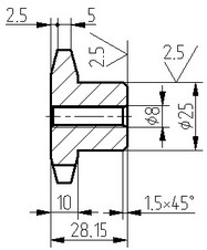
An example of fragment with three fixing points (a transistor)
When using the fragment fixing method based on fixing points, one has to determine the necessary fixing points before creating the drawing. All the rest of the drawing elements must be created relative to the lines defining those points. For example, if we want to use a circle as a fragment, that we could the later place in various locations in the drawings, we should first create a horizontal and the vertical line, and only after that the circle at their intersection point.
Fixing point creation
Fixing points can be created automatically, using the option |
|
As a result, two intersecting construction lines will appear in the screen. Besides, a pair of external variables will be created, x1 (x2, x3, ...) and y1 (y2, y3, ...). The parameters of the horizontal and the vertical construction lines will be given by these variables. Thus, a fixing point is produced in the drawing. When inserting this fragment in an assembly drawing, the system will ask you to specify the fixing point.
If necessary, a fixing point can be defined manually. To do this, just create manually two intersecting lines, a vertical and a horizontal one, and assigne the reserved variable names to their parameters, x1 (x2, x3, ...) and y1 (y2, y3, ...), respectively. The variables must be marked as external in this case.
Throughout the following description, the expression "Create first (second, …) fixing point" will imply performing all steps of a fixing point creation described above.
Let's review most common techniques of creating fixing points of fragments and local coordinate systems in a drawing.
Fragment with one fixing point without rotation provision
Create a fixing point. After that, create all construction lines relative to the vertical and horizontal construction lines that define the fixing point. In the course of the drawing creation, do not use the lines of types "vertical" and "horizontal"; rather, use the types "parallel" and "under angle". If you follow those rules, you'll get a drawing whose local coordinate system originates in the fixing point, and axes collinear with the X-axis and Y-axis of a drawing in which the current fragment is being inserted.
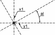
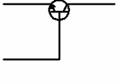
Fragment with one fixing point with rotation provision
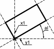
Create a fixing point. Then, create a construction line passing through the node of the fixing point, at an angle to the horizontal line. Assign the slant angle of the line the variable "al". When creating the variable, mark it as external and enter value other than 0 (entering "0" will make the lines coincide with the horizontal line on the drawing, complicating further constructions). The variable "al" will be an external variable of the drawing. Upon inserting the drawing as a fragment, the system will be asking for the value of the variable "al". The construction line passing through the node at an angle to the horizontal line defines the X-axis of the new local coordinate system in this drawing. To create the Y-axis, make a construction line passing through the node and orthogonal to the slanted construction line that is passing at the specified angle to the horizontal line. The slanted line and the line perpendicular to it define a new local coordinate system in the drawing. All further constructions must be based on these lines. As a result, a parametric fragment will be built with one fixing point and the variable "al", that will be defining the slant angle of the fragment coordinate system with respect to the coordinates of the assembly drawing. |
|
To make further constructions with respect to the new coordinate system easy, we recommend doing the following steps. Set the level value equal to "-1" for the vertical and horizontal lines passing through the fixing point. The lines will disappear from display as the construction lines visibility levels are defined by the range from 0 to 127 in the command "SH: Set Levels", while these lines are assigned the level -1 and do not belong in the range. After that, call the command "ST: Set Document Parameters", switch to the tab View and select the value "Visible only" in the parameter "Element selection". By doing so, you set the drawing into the mode in which the elements will not be selectable that are not shown on the drawing.
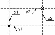
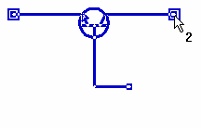
Fragment with two fixing points with rotation provision
The described fragment can be created into different ways. In the first way, the second fixing point defines the fragment rotation and changes the size of the fragment. In the second the way, the second fixing point defines the fragment rotation only, not changing its size.
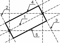
First approach: Create two fixing points of the would-be fragment. After that, you need to create construction line 1 passing through two nodes - the fixing points. This line will be defining the X-axis of the new local coordinate system in this drawing. To create the Y-axis of the local coordinate system, you need to make construction line 2 passing through the node and orthogonal to the line 1. The line passing through the two nodes and the line orthogonal to it define the new local coordinate system in the drawing. All further constructions must be performed relative to the lines defining the new coordinate system in the drawing. Create line 3 parallel to line 2 and passing through the node defining the second fixing point. Next, create lines 4 and 5 parallel to line 1. After that, one can create the necessary graphic lines. |
|
As a result, a parametric drawing with two fixing points is achieved, with the point positions defining the position of the fragment coordinate system with respect to the coordinate system of the assembly drawing. Besides, the second fixing point will be also determining the size of the rectangle. |
|
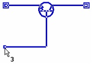
Second approach: All constructions within the second approach repeat those in the first approach, except that line 3 does not snap to the node of the second fixing point, however staying parallel to line 2. |
|
When inserting such a fragment into an assembly, its size will be constant, with the second fixing point defining only the rotation angle of the fragment. |
|
Since T-FLEX system always treats variables x1, y1, x2, y2, etc. as defining fixing points, these names may not be used for defining other drawing parameters.