Face Taper


Face Taper |
|
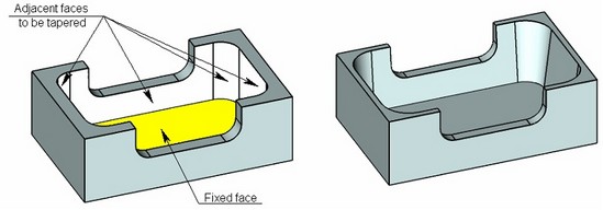
This operation allows the user to taper one or several selected faces at a specified angle, with automatic correction of the adjacent faces.
Face taper can be used, for example, for designing parts manufactured by casting method under pressure. Addition of tapers to the part enables easy extraction of the part from the mold.
General Concepts and Operation Capabilities
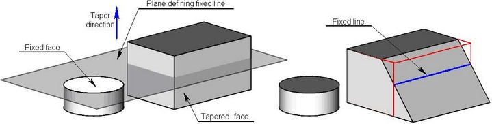
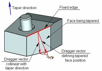
Taper Direction
The direction, in which the taper (slant) angle of the faces is counted, is determined by a vector. This vector can be defined in two ways.
●The first way requires selecting an object, whose geometry will determine the taper direction: a normal to a face, a flat edge, etc.
●Alternatively, the vector can be defined by two 3D points. The second 3D point defines the vector direction.
When designing parts made by parts made by molding, it is necessary to specify the direction of the taper along the direction of the mold separation.
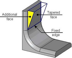
Fixed Edge/Fixed Taper Face
For each tapered face, it is required to specify a fixed edge or a face.
A fixed edge defines a fixed taper line – a line, lying on a tapered face, which does not change its position when creating a taper. Construction of a taper surface takes place with respect to a fixed line. A fixed edge must belong to the same body as a tapered face.
Instead of an edge, it is possible to indicate a fixed face. Intersection of the selected face with the tapered face defines a fixed taper line.
Unlike the fixed edge, the fixed face can be selected on a different body. Once the fixed face is selected, the command creates the plane based on that face, and projects it to the intersection with the face to taper. The intersection line between this line and the face being tapered is the fixed line about which the face tapering will occur.
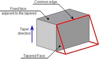
A fixed face can be adjacent to the tapered face. In this case the common edge will be a fixed edge with respect to which the face will be tapered.
Fixed edges and fixed faces are defined separately for each tapered face.
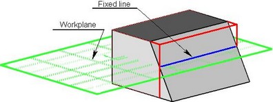
Instead of collection of fixed edges, it is possible to specify one workplane. It will define a fixed line for all tapered faces of the current operation at once. A fixed line of each tapered face will be defined as an intersection of selected workplane with the given face.
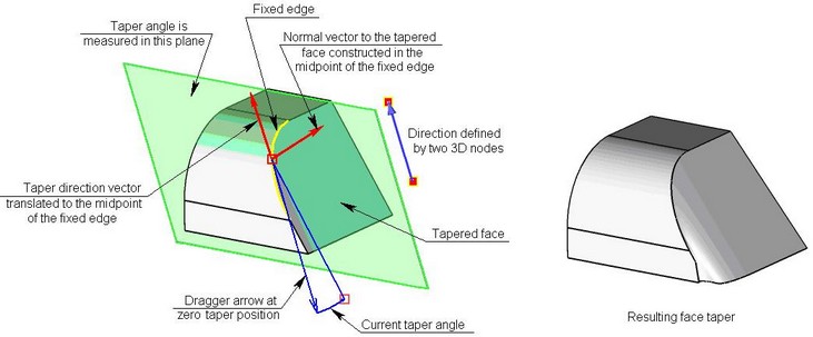
Calculating taper angle
Taper angle of face can be evaluated according to the following algorithm:
●A normal to the face to taper is constructed at each point of the fixed edge.
●The taper direction vector is translated to that point.
●Based on those two vectors, a plane is constructed, in which the taper angle will be counted.
●Next, the vector is determined, that sets the zero taper angle.
The taper angle is counted from the formerly described vector in the plane. This angle defines the resulting vector, through which the surface of the tapered face will be passing.
Processing of Junctures between Tapered and Adjacent to Them Faces
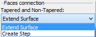
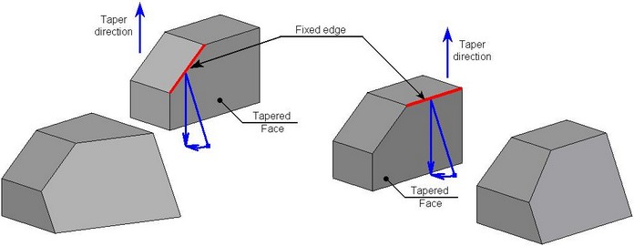
When creating a taper, there is a possibility of creating a gap between the tapered and adjacent to them non-tapered faces. To process these gaps, it is possible to use two methods:
●Creating auxiliary flat faces;
●Extending the surface of the non-tapered face.
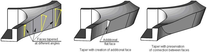
The first way implies creation of an additional flat face for patching the gap at the connection. The second way allows preserving transition between those faces. In this way, a portion of the tapered face will be trimmed by the surface created by extending the adjacent face.
In some cases, creation of the additional face is the only possible way of closing the gap at the faces connection. This exact case is shown on the right-hand diagram.
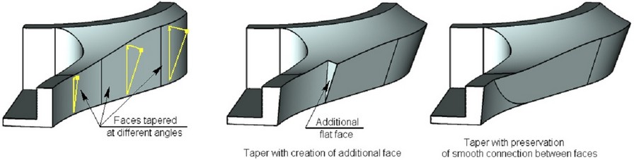
Processing of Junctures between Tapered Faces
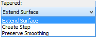
When the adjacent faces are tapered at different angles, a gap can be created between them. For correcting this situation, it is possible to use the following methods:
●Creating additional flat faces;
●Extending the surface of non-tapered face;
●Preserving smooth connection.
Methods of Creating Taper
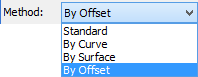
The operation provides various methods of shaping up the tapered face:
●Standard;
●By offset;
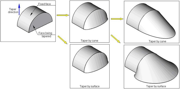
●By curve;
●By surface (see section below “Taper by Offset ”).
By default, a standard method for creating tapers is used. It allows you to construct the tapered surface exactly matching the shape of the original surface and a specified taper angle.
In several cases, the standard method does not allow you to create a required taper. In these cases it is possible to use methods “By curve” and “By surface”. These types of taper match the shape of the original tapered face in a less stringent manner which permits you to construct the taper in cases when the standard method of taper creation does not work. Methods “By curve” and “By surface” differ by the method of resolving ambiguity upon creating the tapered surface. In the first case, for constructing a taper, a tangent to the curve of the fixed edge is utilized, in the second case – the normal to the tapered surface. The tapers “By curve” and “By surface” are usually used for giving a part more aesthetic shape.
In many cases the methods “By curve” and “By surface” give similar outcome. For example, in the example on the figure below, the difference between these methods is noticeable only upon repeated use of the taper operation.
Additional Capabilities of Taper
Taper of Face Relative to Multiple Fixed Faces/Edges
The operation allows tapering the selected face relative to multiple fixed faces or edges. As a result of such operation, the tapered face will be split into two parts. The edges of the resulting faces will have the specified taper angle.
Tapering All Adjacent Faces
The mode of tapering all faces adjacent to the fixed one is provided for quick taper creation. In this case, all you need is just to select the fixed face. The command will automatically determine all adjacent faces for tapering.
Combined Processing of Adjacent Faces
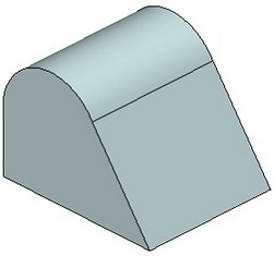
The mode of combined processing of adjacent faces allows the user to create a simultaneous taper for a pair of adjacent faces, when one of the tapered faces serves as a fixed face for another. In a standard mode, an attempt to create such a taper will lead to an error.
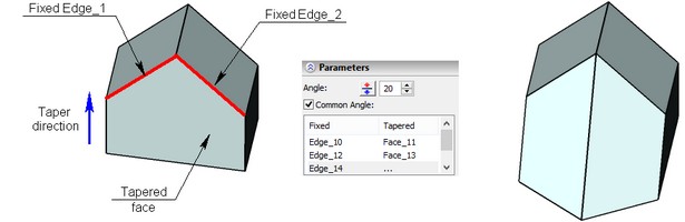
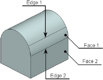
On the figure below an example is shown in which it is desired to simultaneously taper two faces: “Face 1” and “Face 2”. For the face “Face 1”, the edge “Edge 1” is selected as a fixed edge. For the “Face 2” a fixed line has to be defined by the face “Face 1” or the edge “Edge 2”. But both “Face 1” and “Edge 2” will be modified upon taper creation. In this situation, the mode of combined processing of faces can help. By turning it on and indicating “Face 1” as a fixed object for the face “Face 2”, the user can obtain a correct taper of two faces at the same time.
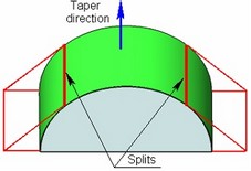
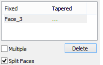
Splitting Faces
This parameter is used in cases when it is necessary to create a taper of the curvilinear face. The command splits the face into patches defining the position for which it is possible to create a taper surface. The tapered patches will pass tangentially to the remaining curvilinear part of the face at a specified angle to the taper direction. |
|
Complex Forms of Face Taper
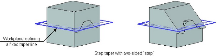
Step tapering
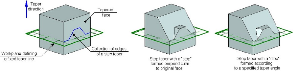
For creating step tapering, the user specifies:
1.Taper direction;
2.Fixed face or workplane;
3.Tapered face;
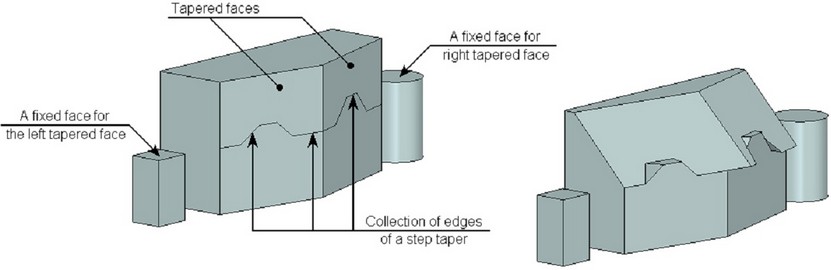
4.A continuous sequence of edges, lying on the tapered face, whose geometry must be preserved upon taper creation. All edges of the specified sequence must be non parallel to the taper direction.
For adding the edge to the tapered face, the command “3ZS: Imprint Elements” can be used.
As a result, the tapered face “turns around” relative to the fixed face/workplane. Along the line generated by a specified sequence of edges, a “step” is formed. Additional faces forming the “step”, can be created by two methods: perpendicular to the original face or at a specified taper angle.
When creating a step tapering, it is possible to create a two-sided “step”.
A step tapering can be created simultaneously on several faces of the body.
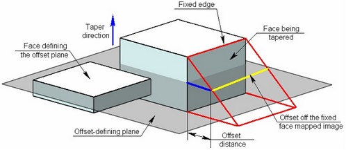
Taper by offset
The method of specifying the taper “by offset” allows the user to determine the magnitude of a taper not by an angle but by an offset of the tapered face with respect to the initial position.
The algorithm of creating the taper “by offset” method is as follows:
●A fixed face or edge is mapped along the taper direction on the plane selected for defining the face offset.
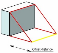
●A specified-distance offset from the mapped face or edge is constructed. In this case, the taper parameter is the offset distance.
●The resulting surface will be passing through the offset off the fixed edge’s mapped image.
Creating face taper
The command for creating "Face Taper" operation can be called by one of the following means:
Icon |
Ribbon |
|---|---|
|
3D Model → Modify → Face Taper |
Keyboard |
Textual Menu |
<3TA> |
Operation > Taper > Face Taper |
Creating Face Taper
After invoking the command for creating a taper (except a step taper and a taper by an offset) it is required:
1.Indicate taper direction;
2.Specify a required number of pairs fixed line/tapered face;
3.Specify taper angle (or a set of taper angles when tapering several faces);
4.Select method of tapering (if necessary);
5.If required, specify additional parameters (the way of filling the juncture between the tapered and non-tapered faces; between the faces tapered at different angles);
6.Complete operation creation with the help of ![]() .
.
Specifying taper direction
For specifying a taper direction by one 3D object, the following option is used:
![]() <D> Select tapering direction
<D> Select tapering direction
This option allows selecting objects in the scene, whose geometry is suitable for defining the taper direction vector. Once an object is selected, its name appears in the properties window.
![]()
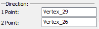
For defining a taper direction by two 3D points, the following options are used:
![]() <1> Select first point of tapering direction
<1> Select first point of tapering direction
![]() <2> Select second point of tapering direction
<2> Select second point of tapering direction
The selected elements are also entered in the properties window. The taper direction is marked by a vector in the 3D scene.
To cancel the direction selection, use the option:
![]() <X> Cancel direction selection
<X> Cancel direction selection
Specifying Fixed Object and Tapered Face
After defining a taper direction, the command will prompt you to define a fixed line of the first tapered face. The following automenu options are used for that:
![]() <T> Select fixed Face
<T> Select fixed Face
![]() <E> Select fixed Edge
<E> Select fixed Edge
![]() <W> Select Workplane
<W> Select Workplane
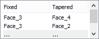
After selecting the respective element, it will be added to the list “Fixed/Tapered” of the command’s properties window.
Then the system will prompt you to select a tapered face. The following option will become active in the automenu:
![]() <F> Select faces to be tapered
<F> Select faces to be tapered
Selected tapered face is also added to the list “Fixed/Tapered” next to the corresponding to it fixed object.
A fixed line (edge, face, workplane) and a tapered face are specified in pairs. Each tapered face must correspond to a fixed object, and vice versa.
Further action of the command depends on the type of the selected fixed object. If it was a fixed edge, then the system will prompt you to select the next fixed edge. If it was a face or a workplane, the system will wait for specification of one more tapered face. Selected earlier face/plane will be, by default, considered as a fixed object for all subsequently selected tapered faces. To select another fixed object, it is necessary to manually activate the corresponding option (![]() or
or ![]() ), select a desired object (face or edge), and then specify a tapered face.
), select a desired object (face or edge), and then specify a tapered face.
Note that in the framework of a single operation, it is possible to specify only one workplane – it will become a fixed object for all tapered faces.
For creating the taper of all faces adjacent to a single fixed edge, it is sufficient, after selection of the fixed edge, turn on the following automenu option:
![]() <A> Select all adjacent faces for tapering
<A> Select all adjacent faces for tapering
All faces adjacent to a specified fixed face will be automatically selected as tapered.
To modify already selected fixed objects or tapered faces, it is necessary to select a desired pair in the list “Fixed /Tapered”, turn on the option of selecting a desired object (![]() ,
,![]() or
or ![]() ) and select an object again.
) and select an object again.
It is possible to delete a specified pair fixed object/tapered face by selecting them in a list, pressing key <Del>.
It is also possible to cancel selection of the workplane with the help of the option:
![]() <X> Cansel workplane selection
<X> Cansel workplane selection
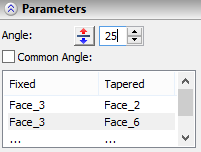
Defining taper angle
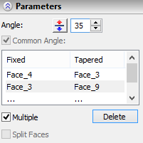
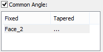
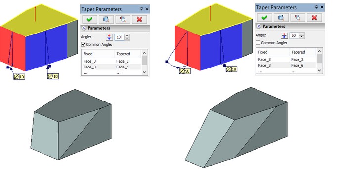
The taper angle is defined by a numerical value in the operation parameters. It can be common across the whole set of pairs of fixed objects and tapered faces, or be defined individually for each pair. By default, the common angle is used.
If for a certain pair fixed object/tapered face, it is desired to define a value of the angle different from the common, it is necessary to perform the following steps:
●In the properties window, click the desired pair of the fixed and tapered objects.
●Clear the check mark on the option “Common angle”.
●Specify the angle value for the selected pair.
The command provides draggers for easy setting of the face taper angles. By using the draggers, you can dynamically modify the taper angle value.
In certain cases the draggers may not be displayed.
A dragger for defining face taper angles appears as two vectors connected by an arc. Both vectors originate from the fixed object (a face or an edge). The direction of the first vector coincides with the taper direction. The direction of the second vector defines the resulting position of the tapered face. The taper angle is set by dragging the tip of the second vector.
A separate dragger is provided for each pair fixed object/tapered face in the 3D scene. If a common angle is used for all pairs fixed object/tapered face, then you can modify the taper angle by any of the draggers. If the “Common angle” option is turned off for any of the pairs, then the dragger position will affect the angle of this pair only.
To change the face taper direction, either enter a negative angle value or push the ![]() button in the face taper parameters dialog.
button in the face taper parameters dialog.
Creating Taper by Offset
For creating face taper by offset it is required:
1.Specify a taper direction;
2.Indicate a fixed taper line;
3.Indicate a tapered face or a collection of faces;
4.Select a face in the plane of which the offset will be created;
5.Specify the offset of the tapered face;
6.If necessary, define additional parameters (the method of filling the junctures between the tapered and non-tapered faces, between faces tapered at different angles, etc.);
7.Complete operation creation with the help of ![]() .
.
Taper direction, fixed taper line and tapered face are specified in the same way as for the standard taper. For specifying the face in the plane of which the offset will be created, it is necessary to turn on the following automenu option:
![]() <O> Select Face for creating taper by offset
<O> Select Face for creating taper by offset
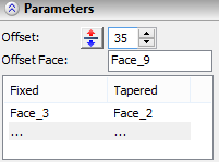
The name of the selected face will be displayed in the command’s properties window (the field “Offset face”). The offset is specified as a numeric value of the parameter “Offset”.
When specifying the face for defining the offset, the parameter “Method” is automatically assigned to the value “Taper by offset”.
Creating Step Tapering
For creating step tapering of faces it is necessary:
1.Specify taper direction;
2.Specify a fixed taper line;
3.Specify a tapered face or a collection of faces;
4.Specify a sequence of edges on the tapered face;
5.Specify taper angle (or a set of taper angles in case of selecting several tapered faces);
6.Specify the method of creating additional faces (by normal or with a taper);
7.Complete creation of operation with the help of ![]() .
.
Taper direction, fixed taper line and a tapered face are specified in the same way as for the standard taper.
For specifying the edges of a step taper, it is necessary to turn on the option:
![]() <S> Step tapering
<S> Step tapering
When activating this option, the command switches to the mode of selection of edges, with respect to which the step taper will be formed.
Selected edges of the step taper will be added to the corresponding list of the command’s properties window. The user can remove selected edge by selecting it in the list and pressing the button [Del].
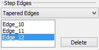
The method of creating additional edges forming the “step” is selected with the help of the list “Edges of step taper”. If the value “Normal” is chosen, the edges will be formed perpendicular to the original face. For the value “Tapered” the faces will be formed at a specified taper angle.
Advanced operation parameters
Taper creation method The method of forming the taper is selected from the drop down list of the parameter “Method”. The taper creation method “By offset” can be set automatically when turning on the option of selecting the offset face (see section “Creating taper by offset”). |
|
Processing connection between faces You can select a method for connecting the tapered face and its adjacent faces, using the parameter “Faces Connection/Tapered and Non-tapered” in the properties window.
Similarly, you can select a method for connecting the tapered faces. |
|
Processing faces together For combined processing of two adjacent faces, it is required to select one of them as a fixed face for another, and turn on the flag “Multiple” in the dialog of the command’s properties. In the same way, it is possible to create a taper for three and more faces. |
|
Splitting face For creating the taper with face splitting, the user has to specify a face which is to be split as a fixed face (a tapered face in this case is not specified) and activate the flag “Split Faces”. |
|
Note that the functionality of splitting faces remains in the command for compatibility with earlier versions of T-FLEX CAD. The currently available "Imprint Elements" command provides various ways of dividing a curvilinear face into pieces for further tapering.