Imprint Elements


Imprint Elements |
|
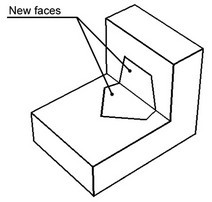
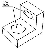
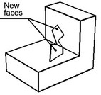
This command is used for defining areas of specified shape on already existing faces. This might be necessary, in particular, for imprinting separator lines and surfaces into a 3D model as part of preparation for FEM analysis. Those elements could be used, for example, for defining forces applied to the model.
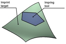
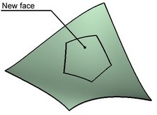
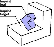
An element being split (the imprint target) can be one or several faces, or a whole operation. Those elements will serve as a basis for creating the new faces. Depending on the splitting method, the shape of the new area is defined based on either the shape of the dividing element (the imprint tool), as Face, Edge, 3D Profile, Operation, or based on the geometry of the imprint target elements.
Using the command
The command for splitting faces is "3ZS: Imprint Elements":
Icon |
Ribbon |
|---|---|
|
3D Model → Special → Faces → Imprint Elements |
Keyboard |
Textual Menu |
<3ZS> |
Operation > Face > Imprint Elements |
To create the operation, do the following steps:
1. Select the splitting method.
2. Select the objects to split (the imprint targets).
3. Select the imprint tool objects (optional).
4. Specify the direction (optional).
5. Confirm operation creation.
Selecting splitting method
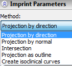
A splitting method defines how the boundaries of the new faces will be determined, and, therefore, what data you need to specify. Select the splitting method from the pulldown list of a combo box located at the top of the property window. Upon entering the command, the method "Projection by direction " is set by default.
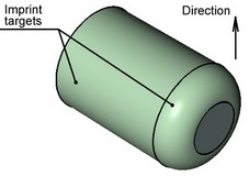
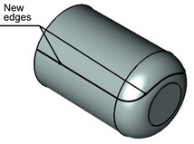
Projection by direction
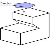
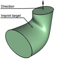
In this method, the imprint tools are mapped on the imprint target objects along the specified direction.
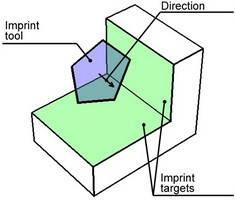
In this method, you need to specify the imprint tool and the imprint targets. Additionally, you need to specify the mapping direction. If the imprint tool is a flat 3D profile, then the assumed direction is along the 3D profile normal. Make sure that the profile mapping direction is towards the imprint target objects. To use a different direction, specify it manually.
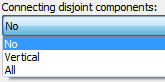
It is possible that the imprint tool mapping occurs along the surface, or even on the opposite side of the surface. In the "Projection by direction" method, upon selecting an imprint tool element, the option "Connecting disjoint components" appears for selecting the mode of joining edges in this case.
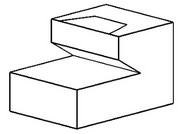
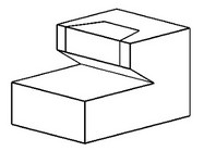
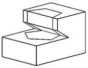
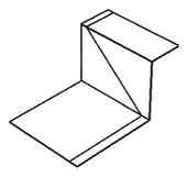
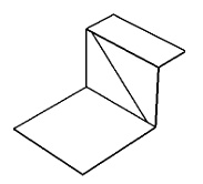
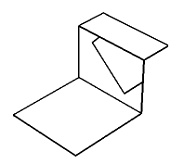
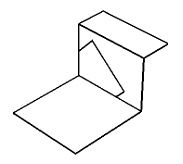
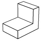
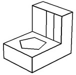
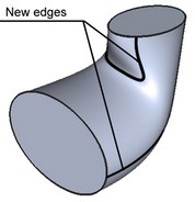
"No" means the system will attempt to create new edges only on the visible faces as viewed in the specified direction. "Vertical" means the system will attempt to create new edges on the faces visible in the specified direction or parallel to this direction. "All" means the system will attempt to create the edges on all faces, including the obstructed faces, as viewed in the specified direction. In this case, the new edges on the obstructed faces must allow a connection with new edges on other faces. The following diagrams show the results produced by each option. |
|
No |
Vertical |
All |
Projection by normal
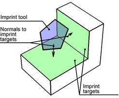
In this method, the boundaries of the new faces are determined by mapping the imprint tool objects on each imprint target object along the normal to the imprint target. All you need to specify is the imprint tool and target objects.
If the imprint target is not flat, the normal changes from a point to a point of the surface. In such a case, the imprint tool object is mapped on the target as follows: each point along the edges of the imprint tool is mapped onto the point of the target that is the origin of the normal passing through the point on the tool.
It is important that all points of the imprint tool had a unique mapping on the surface of the imprint target. The command will fail otherwise.
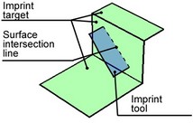
Intersection
In this method, the boundaries of the new faces are the intersection lines between the tool and the target objects.
You need to specify the imprint tool and target objects.
If sheet bodies are selected as the imprint target and tool objects, the combo boxes "Imprint completion" and "Completion method" appear in the property window.
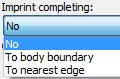
Those can be used in the case when the face of the tool sheet body does not fully intersect the imprint target. In this case, setting "Imprint completion" to "No" results in no new edges created upon executing the command. Alternatively, with the setting "To nearest edge" or "To body boundary", the intersection line between the bodies will be extended (in the first case – up to the nearest edge, in the second – through all body), and that will be the edge. |
|
Edge extended up to the nearest edge |
Edge extended up to the sheet body bound |
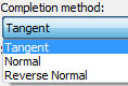
The option "Completion method" lets you specify the direction of extending the edge: either tangent to the edge, or normal (reverse normal). The effect of each parameter is shown on the diagram below.
Tangent direction |
Normal |
Reverse Normal |
Projection as outline
In this method, the boundaries of the new faces are determined by the outline edges of the imprint target object.
You need to specify the imprint target object and direction.
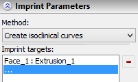
Create isoclinical curves
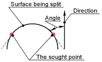
In this method, the boundaries of the new faces are determined by an isocline. An isocline is a line connecting points on the surface being split, in which the tangency line to the surface makes the same constant angle with the specified direction. In 2D, this can be easily sketched (see the right-hand diagram). In 3D, the system builds a set of points – a line.
Isoclines are convenient in mold design. In some cases, an isocline is required for making "Taper"operation.
Selecting imprint target objects
The imprint target are the objects that will be split as a result of the operation.
It is possible to use multi-solid operations and multi-contour profiles as the imprinted elements.
To launch the imprint target selection mode, use the automenu options:
![]() <B> Select target operation
<B> Select target operation
![]() <F> Select target faces
<F> Select target faces
Another way to select is by clicking the mouse on an empty line in the "Imprint targets" pane. After that, you can proceed with selecting the desired faces or operations in the 3D window. Selecting an operation as the imprint target means that all faces of the operation will be selected for imprinting. The system will correctly handle the situations when the number of the original operation's faces changes after regeneration.
To cancel selection use option:
![]() <R> Cancel target selection objects
<R> Cancel target selection objects
Selecting imprint tool objects
Selection of imprint tools takes place only in the following imprinting methods: "Projection by direction", "Projection by normal" and "Intersection". In the other cases, you do not need to select the imprint tools.
It is possible to use multi-solid operations and multi-contour profiles as the imprinting elements.
In the first two cases, you can use the option:
![]() <C> Select tool contours
<C> Select tool contours
The option allows selecting elements (3D Paths, Edges, Profiles, Faces and Loops) that define boundaries of new faces.
With the method "Intersection", use either of the options:
![]() <O> Select tool operation
<O> Select tool operation
(In this case, the system constructs an intersection with all faces of the operation), or the option:
![]() <A> Select tool faces
<A> Select tool faces
(the system considers the selected faces only).
If an operation was selected as the imprint target, then you can select a plane as the tool. In this case, use the option:
![]() <P> Select tool plane
<P> Select tool plane
To cancel selection use option:
![]() <K> Cancel selection of tool objects
<K> Cancel selection of tool objects
Defining the direction
You must specify the direction if using one of the following split methods, "Projection by direction", "Projection as outline" or "Create isoclinical curves". In all those cases, the direction can be specified by selecting two 3D nodes. For this purpose, use one of the options:
![]() <1> Select first point
<1> Select first point
![]() <2> Select second point
<2> Select second point
Alternatively, use the option:
![]() <D> Select direction
<D> Select direction
That allows selecting elements for explicitly specifying the direction.
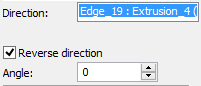
Make sure that the profile mapping direction is towards the imprint target objects, otherwise the application will display a message about an error regenerating the model, upon confirming the operation.
If the mapping direction is away from the imprint targets, use the option "Reverse direction" to flip the direction. The option is located at the bottom of the property window.
To cancel selection use option:
![]() <U> Cancel selection of projecting direction
<U> Cancel selection of projecting direction