New Capabilities of T-FLEX CAD Version 12


New Capabilities of T-FLEX CAD Version 12 |
|
This document presents review of new functionalities, capabilities and improvements of T-FLEX CAD software version 12. This information is primarily intended for experienced users who have good knowledge of the main system tools. For detailed acquaintance with the system functionalities, please refer to the respective sections of Help or User Manual.
Overall Performance Optimization
In process of T-FLEX CAD 12 development the system was analyzed for better performance. As a result the various processes and functionalities were optimized: system start, opening files, reduction of file size, improved graphics performance, accelerated operations for 3D fragments inserting/editing, regeneration of 3D models, reduced number of redraws, etc. Further acceleration was achieved through the use of multi-threading.
Improvements made to the system will significantly improve design efficiency especially for large assemblies.
New 3D Graphics Engine
T-FLEX CAD 12 uses the new graphics engine, which provides significantly higher performance and quality when working with large 3D models in comparison with the previous versions. The new graphics is based on an innovative architecture and leverages the performance of modern video cards. Depending on the performance of the main processor and video card, as well as the structure of the model, an increase in the performance may be from 2 to 10 times or more, compared with the previous version of T-FLEX CAD. Operations with video data were optimized, thus significantly reducing the amount of used memory and providing comfortable work with larger models on the same hardware.
Enhanced graphics performance was achieved both on professional video cards such as NVIDIA Quadro and AMD FirePro, and general video cards, including NVIDIA GeForce and AMD Radeon.
Support for full screen anti-aliasing (FSAA) eliminated jagged edges of geometry, improving image quality.
3D Modeling Commands
Common Parameters of 3D Operations and Bodies
For all types of 3D operations there is now a single set of general parameters - name, level, layer, material, image quality and others. Dialog box for setting these general parameters contains parameters of specific operation, such as name and suppression flag, and parameters of the body, which is the result of this and other operations that form it.
Parameters are located on the "Common" tab of the operation properties dialog box. These same parameters are set when editing properties of the body when calling appropriate command from the context menu of the model tree.
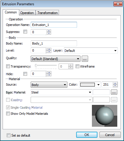
Parameters of operation now present the following set:
«Operation» section.
●Name.
●Suppress – option responsible for excluding operations from model regeneration.
«Body» section.
●Name - name of the body that will result from current and associated operations.
●Level.
●Layer.
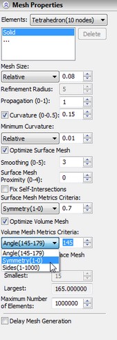
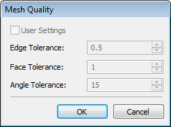
●Quality - option to specify the degree of faceting the model into a mesh of triangular flat faces for displaying models in 3D view. Higher quality increases the number of flat faces, slowing down rendering on large models or not powerful video cards. The predefined seven sets of mesh quality parameters include: Ultra Coarse, Extra Course, Course, Standard, Fine, Extra Fine, and Ultra Fine. We recommend that you minimize image quality of the model. Additional button [...] allows you to specify the exact absolute values for faceting in model units.
When reading models from the previous T-FLEX CAD versions, system automatically assigns the new parameters of image quality based on the overall size and value of "mesh density", which was previously set in parameters of operation. In some situations the automatically assigned quality may be lower or higher than expected, so in these cases it is recommended to fix it manually by selecting the appropriate value of the quality in document parameters (“Customize -> Status” command), or in parameters of the body. You may determine how many triangular facets there are in a model after applying particular quality settings with option "Display statistics information" in "Graphics Settings" dialog invoked by pressing "Graphics Settings…" button on the "3D" tab of "Customize -> Options" command.
●Transparency - check box, slider and edit box for transparency option.
●Wireframe. This option will force the body to be displayed in wireframe viewing mode.
●Hide - option to hide the body in 3D scene, without excluding it from the model regeneration.
All parameters of the "Body" section are available for modification only when the current operation is uniquely associated with the body. If operation generates several different bodies, parameters of this section are not available.
«Material» section.
●Source - parameter that determines the origin of the material. The options are:
- Body. Parameters are set in the current body.
- Parent operation. Parameters are inherited from parent operation.
- Current operation. Parameters are defined in the current operation. This option was introduced for compatibility with previous versions.
●Color – color of the body in wireframe and shading modes.
●Basic material -material for calculating mass properties and engineering analysis. It is also used to define model visualization parameters for displaying in 3D window, unless additional "coating" material specified. Can be assigned to a text variable.
●Coating - additional material for setting visualization parameters for displaying model in 3D window. It allows you to set different material from basic material for model visualization. At the same time basic material will be still used for engineering calculations. For setting the coating material you must set appropriate check box. Coating material can be assigned to a text variable.
●Single coating material . With this option you can force coating material to be applied to all faces of a body. This is helpful when operation contains faces with different materials and you want to have single material for all faces.
●Show only model materials - auxiliary parameter, which regulates the list of materials selection when working with dialog of operation parameters.
Editing Operations with Manipulators
When selecting a body in 3D window system will display special manipulators of operations that form this body. Manipulators allow you to edit directly parameters of operations that form the body without necessity to enter editing commands.
Independent Numbering of Operations
Elements of various types in the model tree are now numbered independently, starting with 1. In the previous versions of T-FLEX there was sequential numbering for all 3D elements - both operations and construction elements. The new numbering is more logical and convenient for complex models investigation.
Rulers in 3D View
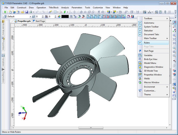
The new command "Show/Hide Rulers" is now available when working in the 3D view. Rulers help to navigate in 3D space and to estimate model size and distance between elements.
Managing 3D Views
Fixing the Set of Views![]()
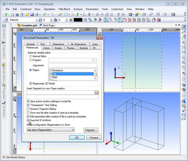
Now you can lock the document window split into views for further sessions with the document. This can be done by setting parameter "Fixed set of windows" on the "Preferences" tab of "ST: Set Document Parameters" command and saving the document. When you open a document or create an additional window for an open document the window will consist of the set of previously defined views. This set cannot be changed. The feature is useful for creating templates with pre-defined set of views.
Fixing the viewing direction (position and orientation of the camera)
New command "3RL: Fix Direction" was added. It can be started from the text menu "View|Rotate" or by using the context (right mouse button) menu in 3D window. Command disables rotation of the scene with the mouse, i.e., fixes the viewing direction (position and orientation of the camera) in the 3D window. The result of this fixation is preventing the turn of 3D scene. But you can resize and move its contents. The setting is saved in the current document and is valid for subsequent sessions of working with this document.
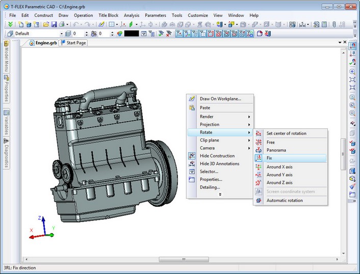
To disable the fixed direction select any other mode of rotation of the 3D scene.
This mode is useful when working with a model from a particular point of view (e.g., front view), as well as when working in multi-window mode.
New Mode of 3D Scene Rotation
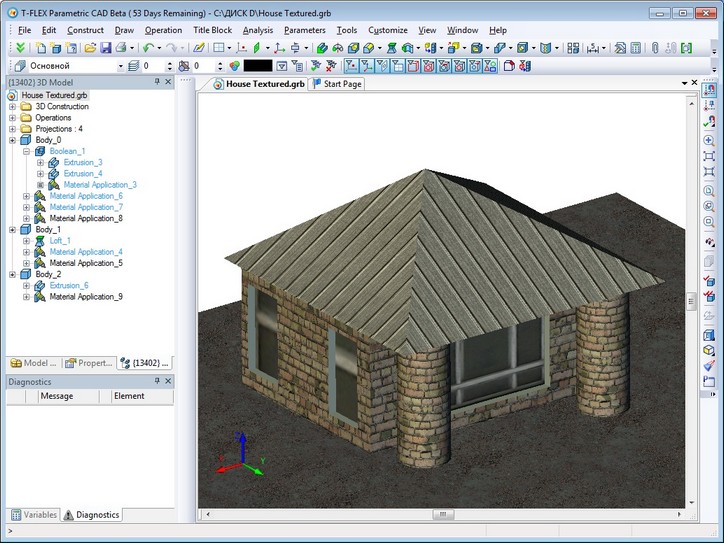
New mode of scene rotation - "Panoramic Rotation" is implemented. In this mode, the plane of axis Z is fixed. This mode reproduces the effect of room examination with camera, which cannot be tilted. Z-axis in this case plays the role of the vertical axis of the room. Panoramic rotation mode can be useful when working with models of buildings, furniture, interiors, etc.
New Mode of 3D Model Viewing
A new mode for displaying 3D models was introduced for “rendering” and “shading” viewing styles - "semitransparent view". This mode displays 3D model in compliance with the rules of the main method of visualization, but all the faces of bodies in 3D scene become semitransparent.
Shading |
Shading with semitransparency |
|
Rendering |
Rendering with semitransparency |
Wireframe Mode
Wireframe viewing mode now can be transmitted to all levels of assembly. Checkbox for wireframe mode in dialogs of 3D operations has three states:
●on (bodies are drawn wireframe);
●off (bodies are drawn according to the viewing mode defined for the whole scene);
●not defined (bodies are drawn according to the settings of the fragment). This mode affects behavior of 3D fragments and Bodies based on 3D fragments. This mode may be inherited for the next operations applied on the same body.
Management of 3D Scenes Using Keyboard
Functional keys for controlling the camera position (viewing direction) now also work in drawing on active working plane mode. For example, you can now rotate 3D scene in the screen plane with buttons <PgUp> (<Ctrl+PgUp>) and <PgDown> (<Ctrl+PgDown>) respectively clockwise and counterclockwise. Default values for the angles of rotation were changed. Without pressing <Ctrl> ration will be at 15°, and with <Crtl> - 90 °. This allows you to rotate the workplane at 90 °with <Ctrl+PgUp> or <Ctrl+PgDown>.
3D Profiles
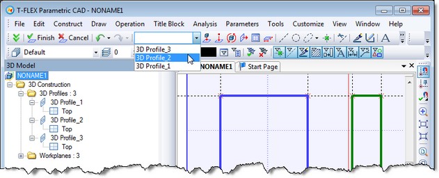
Now it is possible to create multiple profiles on the same workplane by using image lines of different color. Previously, several profiles on the same workplane could be created only by using "Hatch" element.
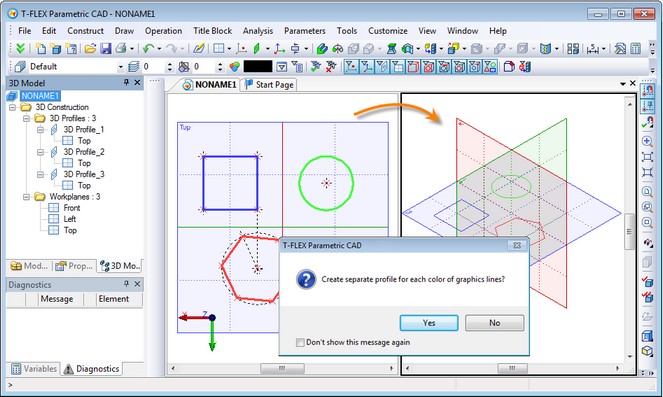
When systems finds lines of different colors when exiting drawing on active workplane mode it will prompt the user to create not one, as before, but several 3D profiles – according to the number of used colors. Each created profiles will be based on image lines of the same color. The color of each profile will match the color of its source image lines except for black color which will result with default 3D profile color . You can change the profile color later in the profile parameters.
This working mode with creation of multiple 3D profiles on a single workplane can be waived. In this case, as before, you can create only one 3D profile from all image lines of the workplane. In the dialog box of 3D profile parameters there is now checkbox "Filter lines by color". It may help you to redefine the profile by setting different color, thereby selecting a different group of image lines of the workplane, or eliminating the color filters for this profile. Then the profile will be reconstructed with inclusion of all image lines of this workplane. |
|
When drawing on active workplane you can find a new control on the main toolbar. It contains the list of available profiles of the workplane. If you choose one of the profiles from this list system will display in large form image lines of this profile, and for the newly created lines it will set the color of the selected profile.
Another new feature of Version 12 associated with the 3D profiles is a set of new commands for editing basic 3D profiles of the model. For operations, faces and 3D profiles in the context menu you may find "Edit Profile" command. This command starts profile editing. It activates the corresponding workplane, shows elements that form the profile and set the appropriate color of image lines, if necessary. The same command is available in the context menu of the workplanes.
Workplanes
Workplanes creating and editing became even more convenient. Now this can be done in transparent mode without having to call a special command.
Workplane Manipulators
When selecting a working plane in 3D scene there are now special manipulators on the side of the bounding rectangle:
●Small manipulators in the form of balls located in the midpoints of the workplane rectangle. They help you to change quickly the visible boundaries of the workplane.
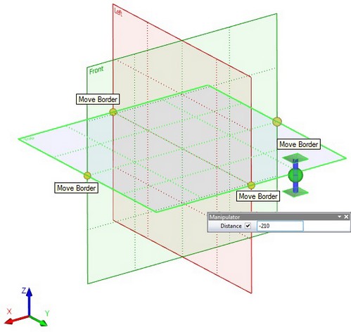
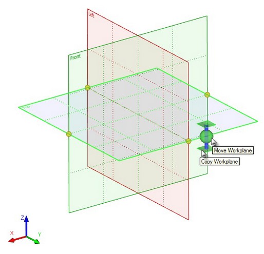
●Big manipulator, which appears in the spot where the cursor was located at workplane selection. It quickly moves the workplane, as well as creates new workplane. Ball in the center - movement manipulator - moves the selected workplane parallel to its original position, the axis with the "pads" on the ends – copy manipulator - creates a new plane parallel to the selected.
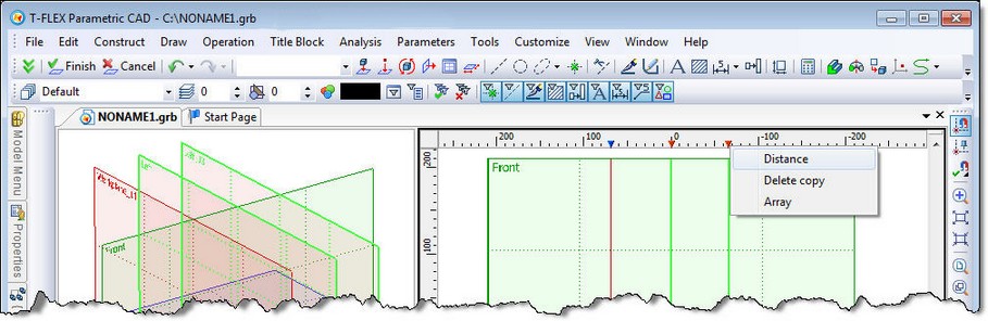
Moving/Copying Workplanes with Rulers of the 3D Window
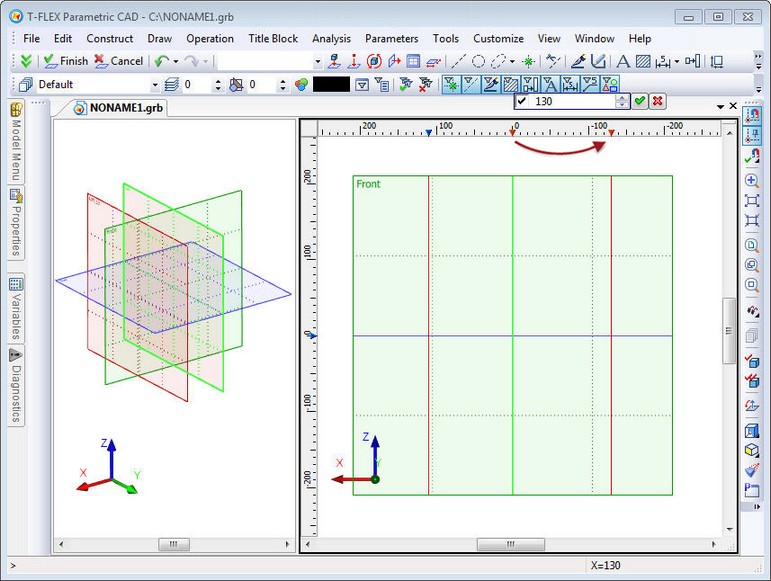
When working in 3D window with activated rulers there is an additional opportunity for fast workplane moving/copying. When workplane is orthogonal to the plane of the current 3D view and has vertical or horizontal position, a special mark on the ruler ( ![]() or
or ![]() ) shows the position of the workplane. This mark is directly connected with the workplane. When cursor is close to the mark, it changes color to red. At the same time the workplane is highlighted. Clicking
) shows the position of the workplane. This mark is directly connected with the workplane. When cursor is close to the mark, it changes color to red. At the same time the workplane is highlighted. Clicking ![]() on the mark opens context menu for the workplane corresponding to this mark.
on the mark opens context menu for the workplane corresponding to this mark.
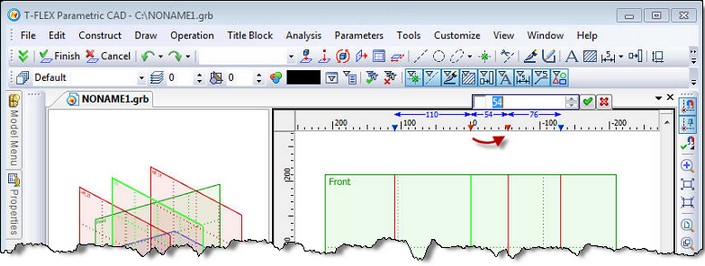
When mark is selected with ![]() and highlighted with red color the moving/copying mode is activated. The dynamic toolbar for specifying the exact value of the workplane displacement pops up. Action that will be applied over the workplane depends on now the left mouse button is used: with the left mouse button pressed (move) or released (copy).
and highlighted with red color the moving/copying mode is activated. The dynamic toolbar for specifying the exact value of the workplane displacement pops up. Action that will be applied over the workplane depends on now the left mouse button is used: with the left mouse button pressed (move) or released (copy).
It is possible to select multiple marks with the help of <Shift> and <Ctrl> keys. All of the selected workplanes can be moved/copied at the same distance (same as the displacement of one plane). There will be also more items in the context menu of the ruler:
●Intervals - automatically move the selected plane so that the distance between all neighboring planes was the same;
●Distance – move apart the selected workplanes at a given distance (only when two workplanes selected);
●Array… – create array of workplanes (only when two workplanes selected).
"Mark Dimensions" mode is available in the context menu of the ruler in 3D window. In this mode, the linear dimensions are shown as the distance between the selected workplanes and to the extreme workplanes on that axis.
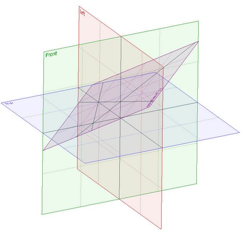
Workplanes Grid
Grid of workplanes, a set of intersection lines of all workplanes, was added to 3D scene. Intersections are shown as gray lines. Visibility of grid is controlled by the new command in toolbar "View" - "Show/hide workplanes grid." By default, the grid is not displayed. Grid nodes of workplane grid can be used for fixing other elements by selecting them as geometric points in 3D operations. This action will result with 3D nodes creation. Grid usage can be very useful for construction of structures made of typical elements (for furniture products, building structures, etc.). |
|
After constructing the "skeleton" of the future product from the workplanes it can be used for positioning adaptive 3D fragments directly at the points of the workplane grid.
New Option in Workplane Parameters
New option was added to workplane parameters - «Show coordinate system». This feature controls the visibility of workplane coordinate system. |
|
New Methods of Creating 3D Nodes
3D Node at Intersection of Three Planes
New method of creating 3D nodes was added to 3D nodes construction command - "Point at the intersection of three planes". To create this node it is sufficient to indicate three geometric planes (faces, workplanes, flat 3D profiles, etc.). Intersection point of these planes will be used for 3D node creation.
3D Node at Point of Workplanes Grid
Now you can create transparently 3D nodes when working with workplane grid. When grid is displayed you can select a point in the grid of working planes, as well as the point of intersection of paths and planes in all operations that require selection of geometric point. 3D node will be created automatically on grid point selection.
3D Sections
New principles of 3D sections
New "fast" types of 3D sections were added to 3D sections construction command. These sections, which are formed without any additional operations on the model, use only the possibilities of video card. The main advantage of these sections is that the geometry of the model in the application of section remains unchanged, and you can work with a model in normal mode - create and edit operations, use the selector to select 3D objects. Thus, "fast” 3D section is a graphical visualization component that provides ease of use with sophisticated products. The performance of "fast" sections does not depend on the complexity of the model geometry, and depends only on the size of the graphical representation.
Due to changes in the principles of 3D sections some restrictions are now applied. Now, in a 3D scene you cannot apply complex sections, for example, based on 2D path, that contains non straight segments and number of segments is greater than two. "Apply Section" command is removed from the context menu of such sections.
When you create a section, you can specify a set of dissected bodies/operations/welds. This set is defined in one of the following modes:
apply to all elements;
apply only to selected;
apply to all except selected.
Section by Plane
Interface for creating 3D sections by plane has changed. Now when you create such section in 3D scene, a green plane is displayed. This is a "blank" cutting plane with a special manipulator in the form of LCS to control the position of the plane. With the help of manipulator and its context menu you can set position of the cutting plane. Also, as before, it is possible to use face, workplane, etc.
Section as Corner or Octant
New types of sections were added - corner and octant.
After starting option of “corner” construction ![]() system will create section with 90 degrees angle. Section planes will coincide with XY and XZ planes of the global coordinate system. Angle may be changed.
system will create section with 90 degrees angle. Section planes will coincide with XY and XZ planes of the global coordinate system. Angle may be changed.
“Octant” ![]() uses planes XY, XZ, and YZ. Corner point coincides with zero of the global coordinate system. With the help of manipulator you can change orientation of the section planes and position of the octant corner point. This can be done by turning and moving axes of the manipulator.
uses planes XY, XZ, and YZ. Corner point coincides with zero of the global coordinate system. With the help of manipulator you can change orientation of the section planes and position of the octant corner point. This can be done by turning and moving axes of the manipulator.
Double-sided Projection when Constructing Paths, Profiles and Imprinting Elements on Faces
When constructing 3D paths and 3D profiles as well as in "Face Imprinting" operation projecting by direction now creates double-sided projection. This simplifies the creation of elements when projected curve crosses the target face. In previous versions of the system in this case user had to forcibly move the projected curve beyond the target face.
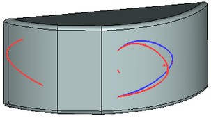
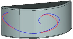
The result of 3D path creation by projecting in T-FLEX CAD 11 (left) and T-FLEX CAD 12 (right)
Red 3D path, the source, intersects with the body, which face is used for projecting
Blue 3D path - the result of projecting
Extrusion
A new type of extrusion target was added in Extrusion operation - "To point". Any geometric 3D point can be now specified as the limit of extrusion. In addition, the operation now has a new manipulator: large double-headed arrow, painted in two colors. The positive direction of extrusion is indicated in red, negative - in blue. The manipulator has context menu (invoked by clicking the right mouse button), which has additional options: -setting step of manipulator; -displaying more items of manipulator - balls on ends of arrow which are used to specify the direction of extrusion by two 3D points; -selection of extrusion limits type (limiting surface, face or Body). |
|
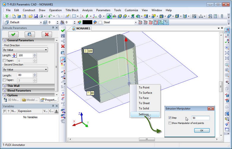
All elements of the manipulator, axis of arrow, ends in the form of cones and point-balls on the ends of arrows hidden by default, have their own functionality. Click on the ball at the end of the arrow takes command to the mode of setting the first and second points of extrusion direction. Click on the arrow moves command to selection of extrusion direction mode. Click on the arrow (cone) or dragging the arrows allow you to set limits of extrusion by distance or by fixing to a geometric point.
Using the new manipulator simplifies and accelerates the process of creating extrusion, making it convenient and intuitive.
Blend
Dynamic Preview
All blend operations now provide possibility to see the results of the operation in dynamic preview. The system displays in color the volume to be removed as a result of the operation.
The new mechanism not only allows to estimate the future result of blend, but also to identify the problem areas of the operation. On those parts of the model, where the construction of blend with the specified parameters is not possible, there is no preview highlight.
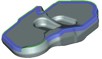
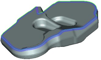
“Curve-Face” Blend
Operation “Blend Faces" now has the possibility to create blends not only between faces but also between a set of edges of 3D profile/3D path and a set of faces. The resulting body will go along the selected edges on one side and faces on the other. To construct such blend it is necessary to specify one set of faces as the right or left wall and a set of edges of 3D profile/3D path as boundary condition. The second wall is not specified in this case.
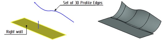
This mode supports only constant radius blends.
“Edge” Blend
Functionality and user interface for "Blend Edges" operation was significantly improved. Refined the Operation parameters dialog was expanded. Now it accommodates several tabs for setting various objects of blending - blended edges and vertices, edges that should not be changed by blend bounding geometry. Automenu behavior also has been changed.
The process of editing the list of blended objects has been simplified. Now by selecting objects in 3D window, you can not only add items to the list, but remove them as well.
In addition, the following new features appeared in operation:
1. Explicit definition of retained edges. Now you can specify edges of the body that will bound the blend surface on. This feature is similar to that in the "Blend Faces" command.
2. When you create blend with variable radius it is now possible to specify null value for radius at any point, and not only for the end points, as before.
3. Setting the trimming geometry - allows you to trim the blend geometry with an arbitrary face, plane or sheet body. This feature allows you to create blends in a variety of complex configurations.
4. Specifying the order of the blend edges in vertices. This feature allows you to change the shape of the blend geometry in vertex, depending on the order of edges blending.
5. Specifying blend topology in vertices. It allows you to create blends in vertices with different shape and geometry - with the use of transitional surfaces or without them.
6. Specifying the order of forming blend surfaces in case of their overlapping on multiple edges.
7. Creating chamfer in vertex. Now you can cut sharp angle at a vertex, without specifying the blend at adjacent edges.
In addition, blend algorithms for complex cases were significantly improved including blending of degenerate and self-intersecting surfaces.
Sweep
"Sweep" operation now has possibility to choose how to interpret the fixing direction by using a non-planar trajectory. You can select from two options: fix by path and direction or fixing of rotation.
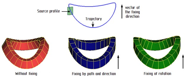
Fixing by path and direction: tangent to the trajectory at each point of the trajectory is projected onto a plane perpendicular to the direction of fixing. The coordinate system of the intermediate section is based on the resulting projection of the tangent to the trajectory and direction of the fixing.
Fixing of rotation: coordinate system of the intermediate section is constructed tangent to the trajectory at a given point of the trajectory and by the vector product of the fixing direction and the tangent.
Texture Management
Texture Files
Management of texture files now is implemented in accordance with the general algorithm for links to external files (similar to fragments, pictures, database files, etc.). This means that:
- texture files can be located in the same folder as the model file that uses it;
- texture files are transferred using "transfer assembly" command similar to other types of files;
- textures can be embedded into the model file (internal textures);
- library name can be used to specify the path to the texture file;
- relative paths, including the names of the folders or higher level references (.. \) may be used to specify the path to the texture file.
Material Application
Command "3AM: Apply Material" was essentially refined. The command was translated to a modeless dialog box of parameters and complemented by functionality. New ways of texture mapping allow creating more realistic models.
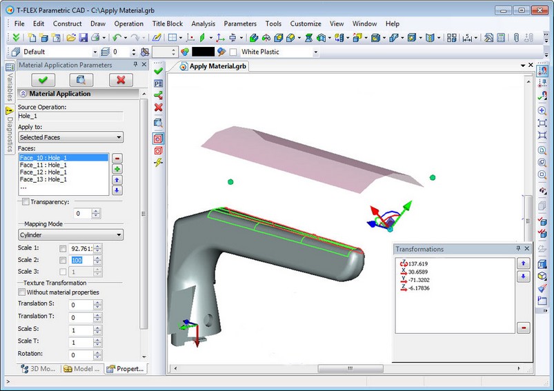
New intuitive manipulators are now used to control the texture mapping and accurate positioning. Different context menu with mapping options will appear depending on which element of the manipulator (plane, point, arrow or arc) there was right mouse button click. All movements of manipulator are logged. Any transformation from the log list may be edited.
For the material application you can select all faces of an operation, the individual face of operation, as well as all faces except selected.
The command supports the following mapping modes for material application:
1. From material - all parameters are taken from the material properties as it was in version 11.
2. Plane – material mapping is done as if the texture is projected along the normal to the plane in which it is located, i.e. in the XY plane of the manipulator.
3. Sphere - material mapping is done as if the texture is located on a segment of a sphere. This option is useful for texturing on spherical and similar surfaces. The parameters of sphere define the scale of texture and controlled by manipulator.
4. Cylinder - the same as sphere, but another type of surface.
5. Box - it is assumed that textures are mapped on the faces of a box and are projected by these faces. For this type of mapping there is an additional scale by the third coordinate. Scale, thus, define overall dimensions of "reference surface".
6. By surface coordinates - mapping useful for curved surfaces. In this mode texture coordinates are associated with the internal coordinates of the surface. It can be viewed as a generalization of mapping at sphere and cylinder. Texture mapping on a surface is always unambiguous, so manipulators are not used.
Deformation
In the dialogs of deformation command it is now possible to define accuracy of calculations. This allows the calculation of complex models that have previously resulted with incorrect geometry.
Interface of deformation command for bending was redesigned. Multi-element manipulator in the form of LCS is now used to specify bending parameters. For all elements of the manipulator there are context menus available with a set of options to simplify positioning of the manipulator and to set bending parameters.
Pipe Path
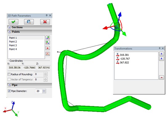
“Pipe Path” creation command was completely redesigned. The command now has more user-friendly interface and enhanced functionality. A new functionality will greatly facilitate the work of engineers, designing pipeline and cable systems.
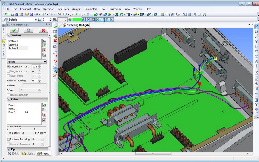
The pipe path can now be presented as a complex 3D path with segments of different types. Path segments may be defined as splines based on points, splines on control polygon or polyline. In addition, you can specify segments on the basis of edge/3D path or surface/face. In one path you can combine different types of segments. For each segment you can separately specify rounding at points, common for the whole segment or individual for each point and the tangent vector at the beginning and end of the segment.
Special multifunctional manipulator in the form of coordinate system is used to set the position of points. This manipulator is familiar to users of T-FLEX CAD from the 3D fragments command. The manipulator can be moved along one or two axes at once (moving it by the coordinate axes), randomly in space (with the ball in the center), rotated around an axis (via the arcs between the axes).
In the context menu for each element of the manipulator (axis, arrow, plane) there is a broad set of commands for changing the position of manipulator in space, fixing it to the existing model elements.
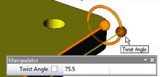
For a segment on the edge/path there is another manipulator available, which consists of the following elements:
●“Location” (of the point at the ends of the manipulator axis) - sets the offset from the beginning/end of the selected object;
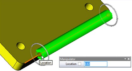
●«Offset» (circles on the ends of manipulator) – sets offset of the new segment from selected object;
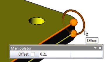
●«Twist Angle» (of the point on the circle). The first manipulator sets angle of rotation of the entire segment around edge/path, the second sets angle of twisting - rotation of the end point about the initial.
All object snaps may be used when defining path points.
System monitors and displays all errors in process of path construction. Also for clarity it is possible to display tags with radii for all fillets.
When creating a path, user now has the ability to dynamically monitor the appearance of the future pipe. In the parameters dialog box there is section "Pipe", where you can specify the diameter of the pipe. In the process of creating a path system will preview the proposed pipe.
Command for creating a pipe path may be invoked by user as a separate command or directly from the command "Operation|Pipe".
3D Arrays
The suppression of an array now brings the original objects to the scene. The change only applies to the case when option "Include Source Operation" is on and only for arrays that do not have option "Separate to Solids".
3D Threads
Internal data storage for threads was optimized. In previous versions of T-FLEX the model contained specific information about the faces on which the thread is available. It took a lot of graphics and operational memory, and greatly increased file size. Now this information is not stored. Now only references to existing geometry of bodies are used for defining threads. This reduces the requirements on the graphics and memory.
To display a thread in the 3D view T-FLEX now uses mechanism of “shaders”. This mechanism is very fast and has virtually no effect on the speed of redrawing the models that have cosmetic threads. In addition, it requires no additional memory consumption. This greatly improves performance when drawing 3D scenes and reduces the requirements for the memory.
Perspective 2D Projections
2D projections can now be displayed in perspective. Check the "Perspective Projection" in the "Basic parameters" tab of the projection parameters dialog box. Dimensions that are based on 2D projections are drawn in accordance with the parameters of perspective.
Parallel Projection Perspective Projection
Detailing Elements in 3D
Mechanism of drawing 3D detailing elements (dimensions, leader notes, roughness symbols) was changed. Now they are drawn quickly and considering removal of hidden lines. This helps to avoid 3D scene overloading. TrueType fonts are now used when drawing the 3D detailing elements.
T-FLEX CAD 11 T-FLEX CAD 12
3D Assemblies
Editing Fragments and Setting Fragment Variables over Levels
Tools for assembly design got further development in T-FLEX CAD 12. Now when working with multi-level assemblies user does not need to "walk" through all levels of an assembly to change the values of external variables of the lower level fragment. Variables of fragments at any level of nesting can be edited directly in the context of higher-level assemblies.
You may select sub-fragments for editing through a level in the model tree or directly in 3D scene. New selection mode was introduced for this purpose - "Select Internal Fragments". In this mode, you can select individual bodies-fragments of sub-assemblies. The set of commands is available for selected fragments to open documents of fragments, detail fragments and edit their variables.
Manipulators of External Variables
User-defined manipulators may be used now for setting values of external variables in 3D model.
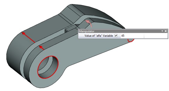
Manipulators of external variables can be used in two ways:
●Change model parameters in the scene . New command was added to visibility toolbar to control the visibility of manipulators in the scene– «Show/Hide Manipulators».
●Change values of external variables on fragment insertion.
You may create and edit manipulators of external variables using command “Parameters\Manipulators”. The command provides possibility to add new manipulators, delete existing ones, and change the description of manipulator.
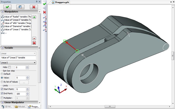
The command supports creation of four types of manipulators:
• linear manipulator - the arrow, whose length is equal to the value of the variable;
• radial manipulator - a ring, the radius or the diameter of which equals the value of the variable;
• angular manipulator - a segment of a circle, whose angular size is given in degrees and is equal to the value of the variable;
• list - for the external variable is a list of valid values.
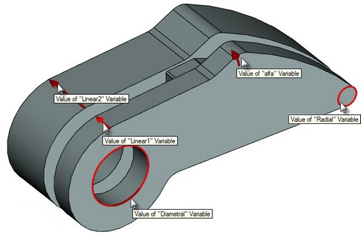
Each type of manipulator has its own properties that define the shape of the manipulator. For example, for a linear manipulator this is the direction and size of arrow, colors on viewing selection and activation.
Also, there are common properties for all types of manipulators: name of external variable associated with the manipulator, comment that explains the appointment of the manipulator, the range of values, and discreteness of values (continuous manipulator, with step, out of the list).
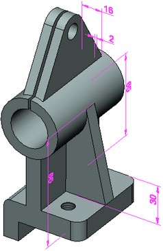
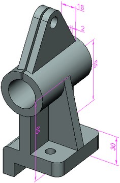
Using Dimensions of Fragments in Assemblies
You can now "raise" 3D dimensions, created inside the document of fragment in the assembly. This can be done by checking "Show for 3D Fragments" option on the “Common ” tab in the dialog box of parameters in the command of dimensions creation or editing.
Dimensions of fragments raised in 3D assembly can be used for two purposes:
●Decorative - they show the nominal of dimension.
●Controlling - such dimensions are used to set the values of external variables by editing their nominal. For this purpose, you must set nominal to "Manual" in dimension parameters and for expression field assign the name of external variable. Editing the value of this dimension in the assembly will be available either when running 3D fragment editing command or via the usual scheme of changes of the control dimensions in “Parameters|Dimensions|Set Value” command.
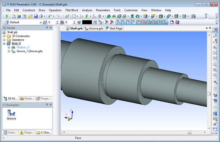
«Smart Fragment» Mechanism
Mechanism of Smart Fragments provides possibility to run arbitrary macro when inserting a fragment. Smart Fragment mechanism allows the development of parametric library parts with the script of their insertions described in the program that is stored directly in the file of library element or external module (DLL). Macro settings of T-FLEX CAD, as well as application programming interface (Open API) allow you to define the settings so that, when inserting a file, a user-defined macro will be executed.
Macro can contain code that implements the necessary logic of user interface when inserting a fragment. For example, an adaptive model of the "Groove" has a set of external variables and adaptive parameter - the circular edge, which should be substituted when inserting the fragment.
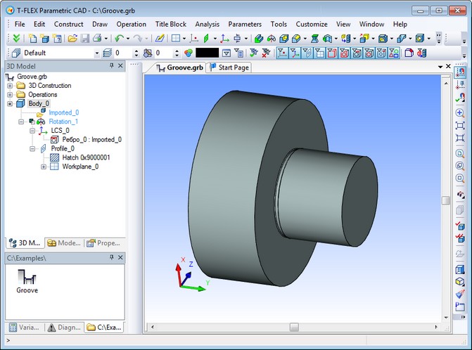
File "Groove.grb" contains macro InsertGroove, which implements the selection of only the circular edges that are at the intersection of the outer cylinder and a flat face. Macro will be started automatically when you insert this groove from library. Instead of the standard command of fragment insertion with full 3D interface, this time a simple command will be started. It allows you to select edges that satisfy special condition and change the values of external variables of inserted fragment.
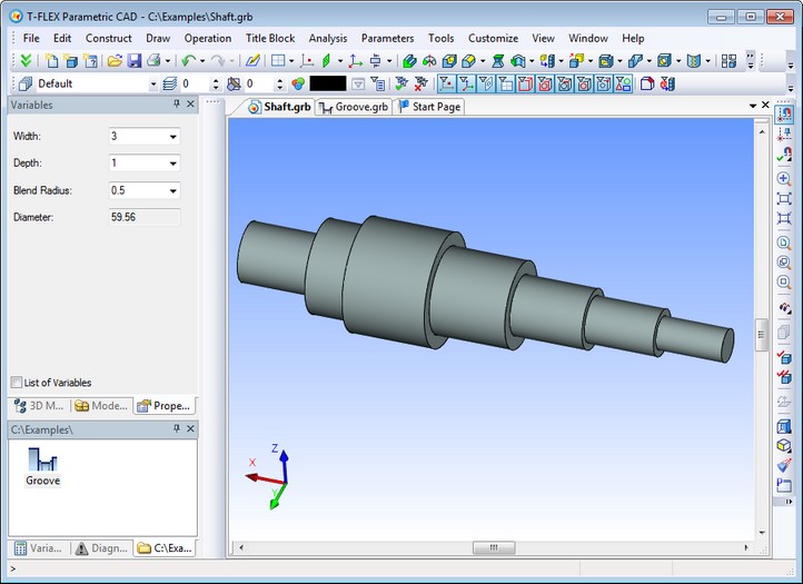
The result of inserting the fragment in this scenario is a groove on the shaft.
This mechanism allows programmers to create user-friendly scenario for inserting fragments in different application areas.
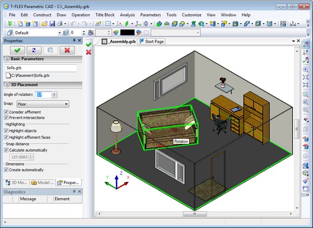
3D Placement
The new method of fixing 3D fragments was added - "3D Placement". The new mechanism allows you to quickly create placement setups in 3D scene using special bindings to the floor, walls, ceiling, and horizontal surfaces. Bindings are defined through connectors with certain parameters.
3D placement mechanism works if there is special “3D Placement” insertion mode defined for 3D fragment in the “Fragment…” dialog box started from “3D” tab of document parameters.
When you insert 3D fragments in 3D placement mode system will dynamically test intersection of bodies to ensure correct placement of the elements.
2D Drafting Commands
New Mode for Displaying Image Line Thickness
A new display mode for thickness of image line was introduced - "Always 3 pixels". When activated, the main lines always have thickness of 3 pixels, thin - 1 pixel regardless of the drawing zoom.
Displaying Actual Values of Document Parameters in the System Dialogs
All dialogs that provide output of "Default" value now have reference output of corresponding value, set in the document parameters. The corresponding value is displayed in parentheses to the right of the main field parameters, such as “Line Spacing: Default (0.5)”.
Highlighting Selected 2D Elements
Now when highlighting selected 2D element system will use different color if the color set for highlighting coincides with the color of element.
System Toolbar
When creating or editing an image line it is possible to set its thickness in the system toolbar.
Copying Properties from Existing Elements
|
You may now copy the properties from the existing 2D element - image line, dimension, roughness, section symbol, GD&T symbol - to another element. This feature is available as |
Node between Two Nodes
New option was added to "N: Construct Node" command: node, dividing the distance between two other nodes in a given ratio.
Axes
Functionality of the command for creating axes "Draw|Axis" was significantly expanded. Now you can create axes of the following types:
●Straight axes at an angle by node ![]() - two perpendicular axis lines of circle (arc of circle or ellipse), one of which passes through a given center.
- two perpendicular axis lines of circle (arc of circle or ellipse), one of which passes through a given center.
●Radial (straight) axis by node ![]() – straight axis of circle (arc of circle or ellipse), passing through a given center.
– straight axis of circle (arc of circle or ellipse), passing through a given center.
●Tangent axis by node ![]() – straight axis of circle (arc of circle or ellipse), perpendicular to the radius, passing through a given center.
– straight axis of circle (arc of circle or ellipse), perpendicular to the radius, passing through a given center.
●Axis by circle and radial axis ![]() – straight axis of circle (ellipse) through a given center and axis by full circle.
– straight axis of circle (ellipse) through a given center and axis by full circle.
●Axis by arc and radial axis ![]() – inclined axes through center for two circles (ellipses) with arc at the size of these circles (ellipse). A special case of this option is inclined axis with arc at size of one circle if second circle is not defined as well as inclined axes with arc to node if 2D node is defined instead of the second circle.
– inclined axes through center for two circles (ellipses) with arc at the size of these circles (ellipse). A special case of this option is inclined axis with arc at size of one circle if second circle is not defined as well as inclined axes with arc to node if 2D node is defined instead of the second circle.
Dimensions
New Way of Dimensioning – Dimension from Axis
New option was added to dimension creation command
|
|
To create dimension from axis it is necessary to specify axis (construction or image line) and object on which to create the dimension. This object may be construction line, image line images, or node.
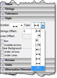
New Mode to Display Dimension - No Lines
Now you can create dimension without lines that is to display it in the drawing only as nominal value. This type of dimension display is useful when you want to place the dimension in particular location on the drawing but without displaying its lines. The mode can be selected from the drop-down list "Type" on the "Style" tab.
|
|
Linking Dimension String to Node
New option ![]() was added to the command of creating and editing dimensions – “Link String to Node”. This option is available when positioning dimension on the drawing. If it is enabled, selection of 2D node (option
was added to the command of creating and editing dimensions – “Link String to Node”. This option is available when positioning dimension on the drawing. If it is enabled, selection of 2D node (option ![]() ) will link dimension string to this node and dimension creation will be completed. If not, as before only guide line will be linked to this node and the command will continue to work.
) will link dimension string to this node and dimension creation will be completed. If not, as before only guide line will be linked to this node and the command will continue to work.
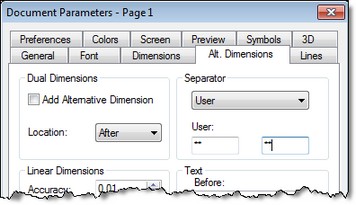
Correction for Alternative Dimension
For alternative dimensions you can now add correction – additional value to the nominal size as compared with the calculated value. The correction applies the same way as for the nominal value: display value = computed value * scale + correction.
When displaying alternative dimensions you can now use any type of delimiter. In the document parameters on the "Alt. Dimensions" tab there is now possibility to select standard delimiters - square, curly braces - as well as any arbitrary separators.
Using Properties of Dimension in its own Parameters
It is possible to use properties of dimension in itself via special construction $(VALUE), where VALUE – name of the property (like in the Measure command).
Setting Connection of Dimension with another Dimension
Now you can associate dimension with another dimension. New option |
|
This functionality can be used, for example, to display dimensions on a simplified drawing the same as on the exact product drawing.
Leader Notes
Command for creating leader notes was substantially revised. Interface became more convenient. All parameters of the leader note are edited seamlessly with the properties dialog box. All the graphics settings (coordinates, offsets) are edited directly in the drawing window with manipulators (markers).
Leader note can now have a multiple leaders. Each leader can have its parameters. Each leader can have an arbitrary number of intermediate points, which can be conveniently edited in the command of creation and editing using object snaps and the properties dialog box. Text position and special symbols of leader notes are now controlled by means of special points-manipulators.
Section View Symbol
Command "Draw|Section" now has option for creating section symbols based on geometry of 2D path. Thus, it is possible to create section symbols along the arc of a circle, as well as along the complex path, including lines and arcs of circles.
GD&T Formlimits, Datums
The command for creating GD&T and datum symbols was completely redesigned. The command is now using a convenient modeless dialog, similar to most other commands of the system. Functionality of the command was expanded - now it allows you to create tolerances and datums with any number of arrows, and fix them directly on 3D models. Tolerance with the leader or datum with leader now present a single element with common dialog. Convenient manipulators were added to create leader with breaks.
Clearing Background of the Drawing Elements
For dimensions, roughness and leader notes now it is possible to clear background under individual elements of the objects. In the parameters of these drawing elements the following check boxes for clearing background were added:
●for dimension: under each arrow separately;
●for leader note: under arrow and corners;
●for roughness: under arrow and leader;
●for GD&T symbols: under arrow, line, leader.
Assigning Name for Drawing Element
You can now assign name for drawing elements – dimensions and leader notes – in commands for editing these elements. Element name may be helpful for using various properties (measurements) in variables editor as well as for searching named element via API calls in macro programs and applications.
2D Copies
New Command for Shortening and Extending Copies of Image Lines
There is a new "Shorten/Extend" command in the context menu of image line invoked by right button mouse click. Command allows you to change the length of the visible part of the line. Extension function is available only to straight segments and arcs.
The new command simplifies image lines editing on the drawing views. For example, with the help of this command straight segment in the image of the groove can be easily and quickly converted into a rounded fillet. Or you may cut lines, beyond the limits of the cutaway view.
Part of the image line that must be modified is indicated by 2D nodes. At the beginning of the command you should indicate the part of line you want to change, then - the node that defines a new point of the line end. For closed curves you must specify two nodes and part of the line that you want to keep. Used 2D nodes can be located on the line or at some distance from it. In this case, the end of the line is defined by a point on the line closest to the selected node.
Context menu for the line modified with “Shorten/Extend” command contains command “Restore”. It allows restoring the original view of the line. |
|
New Algorithm for Deleting Original Elements of Copies
Now when you delete some elements used for creating a copy or an array in “Delete selected and related elements” mode, corresponding copied elements are excluded from the copy retaining the copy element itself.
Deleting in “Delete only selected elements” will result with creating of “free” non-associative elements retaining copy result unchanged.
Drawing Views
Fast Drawing View Activation
Drawing view can be now activated by simple double click without calling special command.
Updating the Contents of a Drawing View
Now it is possible to renew the contents of the drawing view after editing the source elements. Use command "Update Drawing View" from the context menu of the drawing view for this purpose.
Broken Views without Projections
To minimize the number of steps for creating drawings, the possibility of creating broken views was added to 2D drawings without projections. Mechanism for specifying and applying breaks on drawing views is similar to that is used in the broken views on 2D projections.
If there is a break on the drawing view it is drawn with the break on the page of display and without the break on the drawing view page. If you activate the drawing view either in transparent mode on the target page or in a separate window, it is drawn without the break.
The command of editing drawing views now has special mode for editing breaks. In this mode the drawing view is drawn without the break, and breaks are shown as shaded areas.
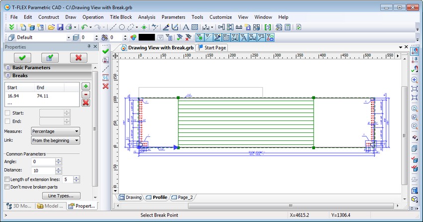
Direction of the drawing view breaks is defined by "Angle" in the parameters dialog box or by construction line. Positions of breaks can be adjusted with a mouse or through dialog of parameters. Positions of the start and end are measured along the direction of the breaks in units of the displayed page or as percentage of image size. The image size is calculated in the direction of the breaks. Position of breaks can be defined with 2D nodes.
Position of the breaks may be calculated from beginning, middle, end of the image area, or from the base point of breaks. The base point is the center for shifting the image. This point may be defined in coordinates in units of the displayed page or with 2D node. The initial position of the base point is in the middle of the image area.
By default, the boundary lines of breaks are determined by the extreme lines of the image, separately for each side of each break. Detailing elements (dimensions, text, etc.) are not counted when determining the boundaries lines of the break, as well as fragments that have special display mode - without clipping. The boundaries of the break can also be set directly by two construction or image lines.
Elements of the displayed page of the drawing view can be divided into 2 groups:
●main drawing elements - image lines, hatches, fragments;
●detailing elements - dimensions, leader notes, text, etc.
Main elements of the drawing view are displayed with clipping on the boundaries of breaks. The detailing elements are displayed by default without clipping over the main image. Only those elements that do not fit in the breaks are displayed.
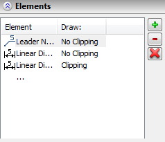
If necessary for individual drawing elements and fragments you can assign particular mode of displaying on the drawing view - with or without clipping. To do this, use “Special Elements” in the dialog box of parameters. On the drawing view elements included in the list are marked with a frame, and the elements for which "With clipping" option is set are marked by oblique lines. Display mode can be changed by clicking element in "Draw" column.
There are the following rules for displaying dimensions on the drawing views with breaks:
●Dimensions whose boundaries lie in different separated areas of the drawing view, parallel to the break, are drawn with nominal corresponding to the real value.
●Dimensions whose boundaries lie in different separated areas of the drawing view, not parallel to the break, are not drawn.
Control Elements and Model Parameters
Control element of "Button" type now has new options-actions: "Open Document", "Edit Fragment Variables". Now with a button in the custom dialog of parameters it is possible to open new documents as well as assign values of variables over the level when you insert the model as a fragment.
In the document parameters on the "Preferences" tab there is a new option - "Regenerate 3D Model". It is responsible for 3D model regeneration when you click [OK] in the dialog of external variables (command "M: Model Parameters").
Another new option on "Preferences" tab of document parameters is "Edit parameters after creation if file is used as a template". It provides possibility to start the dialog of external variables when creating a new document from the prototype.
Text
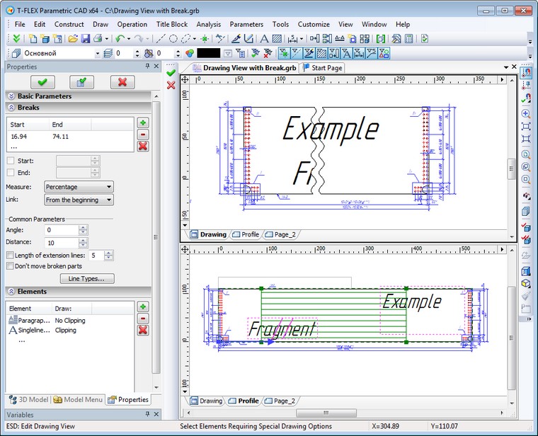
Taking into Account Italic Font when Formatting Text
New option was added in the parameters of paragraph-text, multiline text and tables - "Correct Length of Italic Text". This check box controls the mode of considering italic type when formatting text that contains indices or fractions. For new text it is enabled by default, and disabled for text created in the previous versions of the system, so that previously created text remain unchanged.
Inserting BOM Position Numbers into Text
Functionality for inserting position numbers of BOM in the text was implemented. Command "Insert Position" was added in the editor of multiline and paragraph text. It lets you select the object of BOM and use value of position of this object in text. If you change the number of position of the selected object, it will be updated in the text.
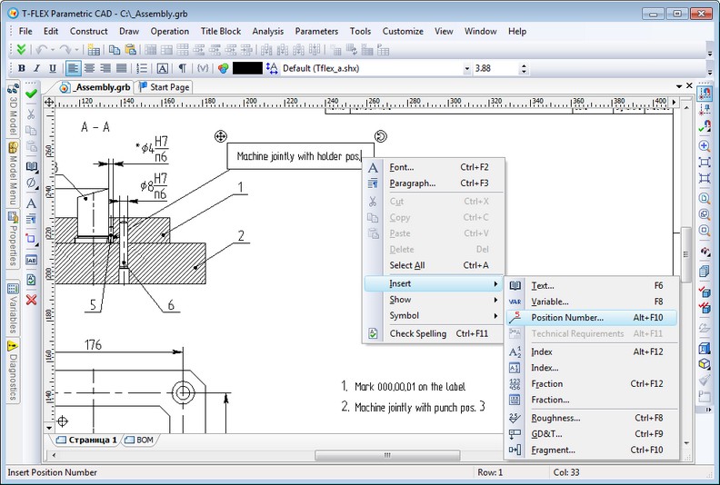
BOM position in the text is a special element of text that contains the link to the record in BOM. Manual editing of this element is not available, you can just delete it. Use command "Tools|Bill of Materials|Update Positions" to update numbers in text simultaneously with updating position numbers in the leader notes.
General Changes
New Version of Parasolid Kernel
System now uses Parasolid geometric kernel version 24.1. Due to kernel upgrade improved handling of complex cases in all types of blending, Boolean, tapering, shelling and other 3D operations was added. In particular, various cases are now processed in more enhanced way, such as self-intersections of surfaces or tangent cases. The accuracy of calculations of geometric objects in the number of algorithms was seriously improved. There is now support for multiple cores in various calculations which improved general performance. New options in existing modeling commands were added.
New Graphics Settings in System Options
Dialog box for graphics settings on “3D” tab of “Customize|Options” command was modified. Instead of “OpenGL…” button there is now button “Graphics Settings…”, that invokes renewed dialog with the following parameters:
●Graphic Mode – one of the three modes: VBO (Vertex Buffer Array), VA (Vertex Array), Software emulation. The last mode is for the case where video card is either outdated or is not completely used, i.e. in Remote Desktop mode, so that graphics cannot be hardware accelerated.
●Antialiasing – number of pixels to calculate antialiasing, mechanism for smoothing jagged edges. By default this parameter is disabled (set to 0). Enabling this parameter will improve image quality but may slow down graphics.
●Vertical Synchronization. If enabled, the frequency signal is synchronized with the monitor refresh rate. This mode is the most ergonomic.
●Transparent surfaces drawing.
●Display Statistics Information. If this option is enabled, then the top left corner of 3D view will display information about the number of objects of different types in the scene and rendering speed in frames per second (fps).
Main Application Window Themes
For greater convenience T-FLEX CAD 12 is able to change the theme (style) of the main application window. In the context menu of the main window you may find "Theme" item, allowing you to select the desired style: Metallic, Magic, Aqua, Black, Blue, Silver, Flat, and Classic.
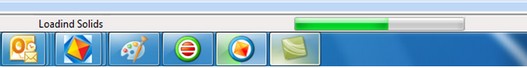
Displaying Progress of Model Regeneration in Windows 7 Taskbar
During continuous model regeneration in Windows 7 the taskbar displays the progress on an application button.
Support for Windows 7/Windows Vista Style in File Open and Save Dialog
File selection dialog now works in the style of Windows 7/Windows Vista. The left pane displays a list of root folders to open libraries. In Windows XP, the functionality has not changed.
T-FLEX CAD 12 Interaction with Windows 7 and Windows Vista Explorer
Search in Windows 7/Windows Vista can now receive text information from the T FLEX CAD documents. This information comes from the text, dimensions, leader notes, BOM specifications, etc.
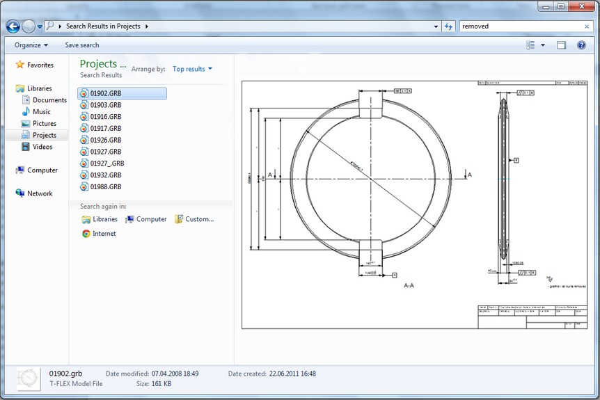
Windows 7/Windows Vista Explorer can now fully preview T FLEX CAD documents on the preview pane.
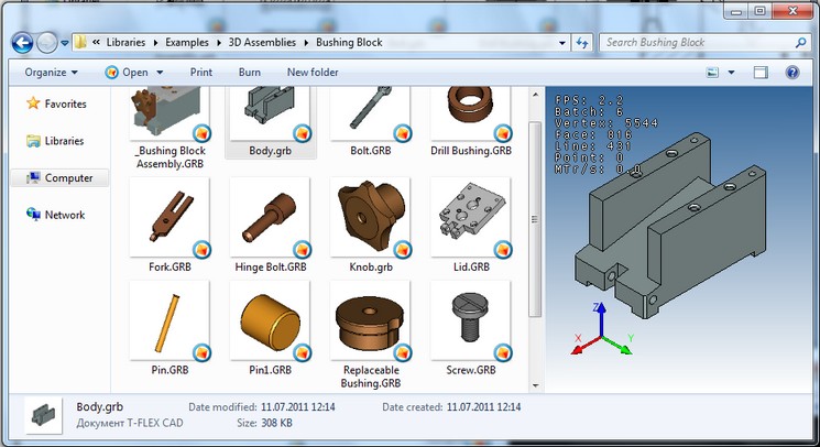
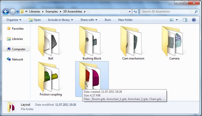
To display the slides as large and medium-sized icons Windows 7/Windows Vista Explorer now uses an image, automatically obtained from the T FLEX CAD.
Single Keystroke Combination to Confirm Input
All 2D and 3D commands that require confirmation of entry (button [OK] in automenu) now support single key combination <Ctrl+Enter>, confirming the entry. This combination works when input focus is either in the drawing (model) view or in the Parameters dialog.
The previous keyboard shortcuts (<Y>, <End>, <F5> and others in different commands) assigned to the OK button are also valid.
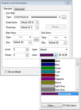
Setting Color Parameters
In the dialogs of parameters of 2D commands and 3D operations it is now easier to set arbitrary values for color. The color components (R, G, B) are output, separated by commas.
Automatic Activation of Page when Editing Elements
When you start "Edit" command for 2D elements from one of the auxiliary windows (diagnostic window, 3D model structure, etc.) document page containing the desired element is now automatically activated. If at the time of the command call 3D window is active, system asks the question "This command cannot be executed in 3D window. Open 2D window to edit object?". In case of confirmation a new window with the correct page will appear on screen.
Variables Editor
“Variable Usage” command was added to context menu for a variable in variables editor. It invokes dialog that shows the usage of this variable in the model. The style of this dialog is similar to that is used in the command "Parameters|Links...".
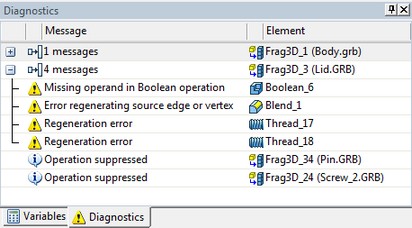
Diagnostic Window
Diagnostic window was significantly redesigned. The changes affected both the appearance of window and its functionality. Diagnostic window is now created independently for each document open in T-FLEX CAD. This ensures fast switching between documents and retaining window settings for each document.
The appearance of the message table in the diagnostic window is now determined by the user. You can choose the columns to be displayed in the table, change the rules for sorting and grouping messages. All these actions are carried out by using the context menu of the title bar of the diagnostic window.
Messages preventing (hiding) is now active only for a particular document. Also as part of one document (model), you can choose whether to hide all the messages of some type, or only messages from a particular model object.
The possibility of grouping by folders messages coming from different fragments is introduced for convenience of operations with assemblies.
Diagnostic window now displays errors of variables, previously displayed only in the variables editor. In the context menu of such messages the command "Variable Editor" is available. It starts variables editor and sets focus to the corresponding variable.
Groups
New mechanism for the "groups" was developed. It allows you to logically combine several elements (both 2D, and 3D) into a single entity - a group. There is a new command to create and edit groups - "EU: Edit groups of elements".
Group is a named logical aggregation of several elements, created by arbitrary rules. Grouping allows you to work with mixed elements as a single unit: select, move/copy as a single object, set the common properties, etc. Using groups allows you to organize the structure of the drawing (3D model), and prevent unwanted editing of its separate components.
Each group in the document has a unique name. Any object in the drawing or 3D model can belong to only one group. Group itself can be included in another group, thereby creating a hierarchy of groups of any complexity.
Since the objects are combined into a group, the system will operate with them as with a single unit. When you move mouse on the screen to the element included into some group, the entire group will be highlighted as a whole. When you select an item that is included in the group you automatically select all elements of the group. If necessary, you can select separately any element of the group, using ![]() with pressed <Alt>. When you select element this way you can change its properties and even the geometrical parameters.
with pressed <Alt>. When you select element this way you can change its properties and even the geometrical parameters.
The composition of groups can be edited by adding new elements to them or removing already included.
Groups of elements can be created in two ways:
●manually by using the "EU: Edit group of elements" command;
●automatically when performing various actions, such as exploding 2D copies/arrays, 2D fragments, drawing views, or 2D projections.
With the exploding of copies, arrays, drawing views, fragments, projections, you are prompted to merge the objects obtained into the group. The group name is automatically set as the name of the destroyed object.
When selecting elements of the group outside of any command there are commands for editing and exploding group available in the context menu.
Creating Technical Requirements without Drawing
New command “Technical Requirements” (“Title Block | Drawing Notes | Technical Requirements…”) allows you to create technical requirements without linking them to the drawing, for example, in document containing only 3D model. Such requirements are stored in the document as a multi-line text, but do not appear anywhere.
To display the data created with this new command on the drawing, it is sufficient to use command "Title Block | Drawing Notes | Insert...”. By default, the written text will contain technical requirements previously defined in the document.
The new command was added to the context menu when editing text, which allows inserting the text of document technical requirements.
The list of document technical requirements can be exported to a file and then imported to any document.
“Measure” Command
Functionality of “Measure” command was sufficiently expanded. In measurement for two elements, in the case of selecting two 2D nodes or 3D points, you can now calculate the distance between these points by individual axes. In variables editor you may use function measure ("Node_1", "Node_2", "DX") for this purpose. For Y-axis use designation "DY", for axis-Z - "DZ".
"Measure" command now allows you to get the values of text parameters for various 2D objects, for example, "Text of the leader note," "Dimension tolerance", etc. In case of text parameter, if you create a variable, function get() is replaced by the function tget(). Accordingly, in this case, user must create not numeric, but text variable.
For fragments it is possible to get the values of text variables. Previously, the command supported only numeric variables.
There is now option to get the values of connector.
Bill of Materials
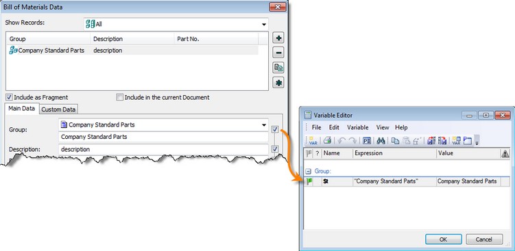
Assigning Variable BOM Group Name
When setting data for BOM there is now possibility to assign variable or compound string to the full name of BOM group like it is supported for other fields of BOM data.
The value of the variable or string should contain the name of the group in the following format: "Group\Subgroup \ ...". The name of the group should match system database of BOM groups, otherwise the group will not be assigned. When you enter the full name of the group in the edit box, system looks in the database of groups and if the group is found, it will be selected in the list.
Mechanism of Storing BOM Groups
T-FLEX document, together with the BOM table now stores settings of the BOM groups (group name and ID of the parent group). When you open a document, at first the system database of BOM groups is loaded. Then groups of the BOM table settings are added. In case of coincidence the names of groups from system database will be replaced with the names specified in the settings of the particular BOM table. Thus, when you open a document saved in T-FLEX CAD 12 on another computer with different system database of BOM groups there will be no problem with undiscovered or incorrect groups and you will not need to transfer the database of groups to this computer.
The groups are now assigned in BOM table by their full names, if the data in corresponding fragments is given in full names of the groups, otherwise - the old way by ID. Full names of groups are now stored in the fragment when you edit BOM data through the dialog of BOM data and the current database of BOM groups is used. Substitution of the full names from the current system database of BOM groups is performed when reading data from T-FLEX documents of the previous versions.
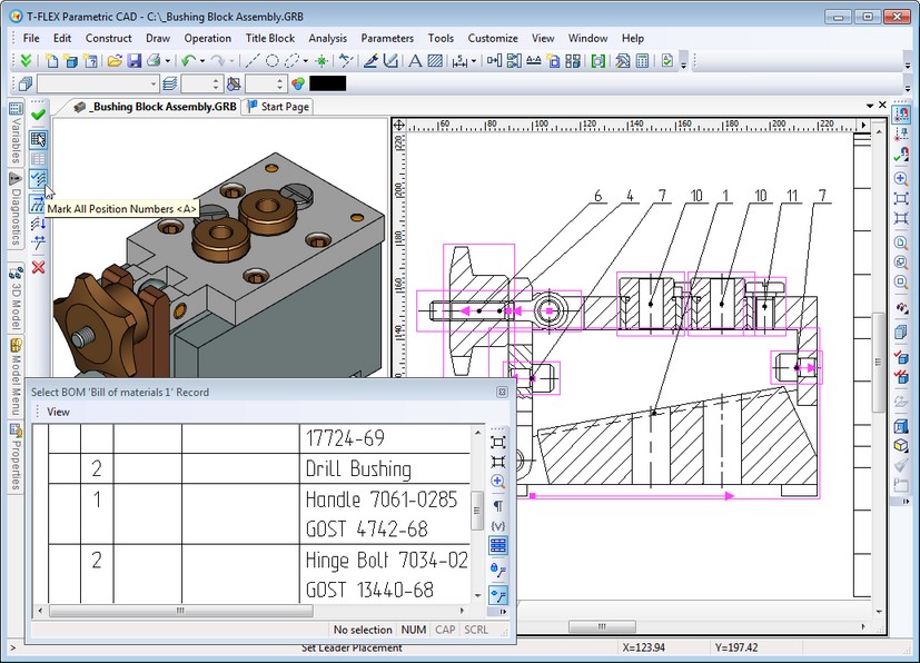
Automatic Placement of BOM Positions on 2D Projections
Option “Mark all position numbers” was added to "Tools|Bill of Materials|Positions" command. For automatic positioning on 2D projection it is sufficient to select 2D fragments (or image lines of 3D fragments projections) corresponding to the positions in BOM table, and specify the location of leader notes being created. Resulted leader notes may be edited in usual way.
Setting Link between Position and Particular BOM Table
For a document that contains several BOM tables, there is now possibility to uniquely set link between positions and particular BOM table. Changing active BOM table will not affect update of positions in other tables. Thus you can put positions for one BOM table, then change active BOM table, and set positions for the new table.
To associate position with particular BOM table use button "Save link for positions" in the dialog of selecting BOM records for placing positions. By default, this option is disabled.
Exporting BOM Tables to Excel Format
Command for exporting BOM tables now has possibility to save data to Excel document in xlsx format using OpenXML library, that works with MS Office 2007 and 2010 documents and also under Windows x32 and x64.
Databases
New Database Editor
Database editor built in T-FLEX CAD was completely redesigned. Now the editor's dialog box is modeless. Additional database editor window created in the current document appears on screen when there is a call to "Parameters|Database" commands. This window contains table of the database and the list of databases in the current document. You can quickly switch from one database to another.
Thanks to the new mechanism the simultaneous operations in the main document window (drawing, 3D model) and database editor are now possible as well as simultaneous editing of several database tables of the same document.
All basic commands for working with database were united in the special set for the main toolbar - "Database", which becomes available when database editor is active.

Copy/paste operations are now supported when exchanging data between several database windows or external data sources. The order of the columns can be changed simply by dragging their headings.
When working with the database editor there is now uniform transparent mechanism for cancellation/restoring of actions - undo/redo.
New Mechanism for Storing Reference Databases
Storage mechanism for reference databases was improved. Data from external sources (databases by reference) is now stored within the document and is updated as needed or upon request. This speeds up operations with the data, and also helps to retain parametric models that use reference database in case of database file loss. Parametric models continue to work, and the link to the file will be automatically updated when the file becomes available.
You may select one of three modes for updating reference databases:
●Auto. The update will be performed when opening model file.
●On full regeneration. The update will be performed on full regeneration with all links update.
●Manually. The update is performed by calling manually special command “Update reference database contents”.
The list of possible external data sources was expanded. Now reference database may be linked with T-FLEX DOCs dataset and ODBC (SQL) database query.
Graph Editor
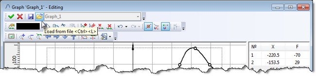
Graph editor changed its appearance - it is more modern and fully complies with the interface of the system as a whole.
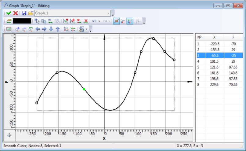
Command "Load from file" was added to the dialog for editing graphs. It allows replacing the edited graph with a different graph from an external file *. tflaw. As a result of the command all original points will be removed and replaced with the other.
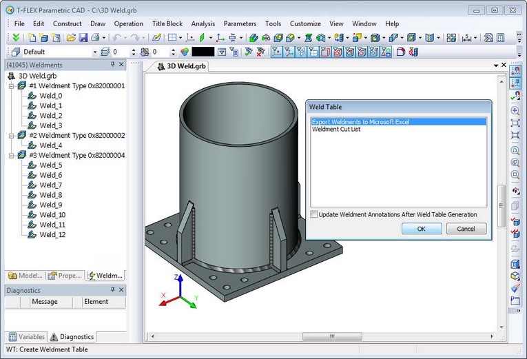
Exporting Weld Table
Command-macro for exporting weld table to Excel (xlsx) was improved. Now it does not require Excel application for its operations.
T-FLEX Analysis
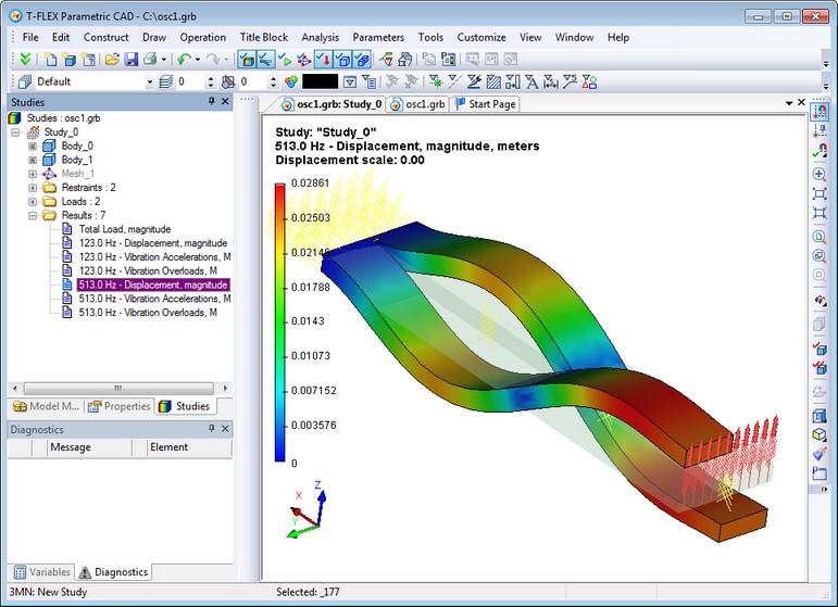
New Study – «Forced Oscillation»
New type of study - "Forced Oscillation" was added to T-FLEX Analysis application. This study helps to predict the behavior of structures under the influence of external factors, which vary harmonically. External factors include forced and/or kinematic excitation. The study may also consider the effect of system damping.
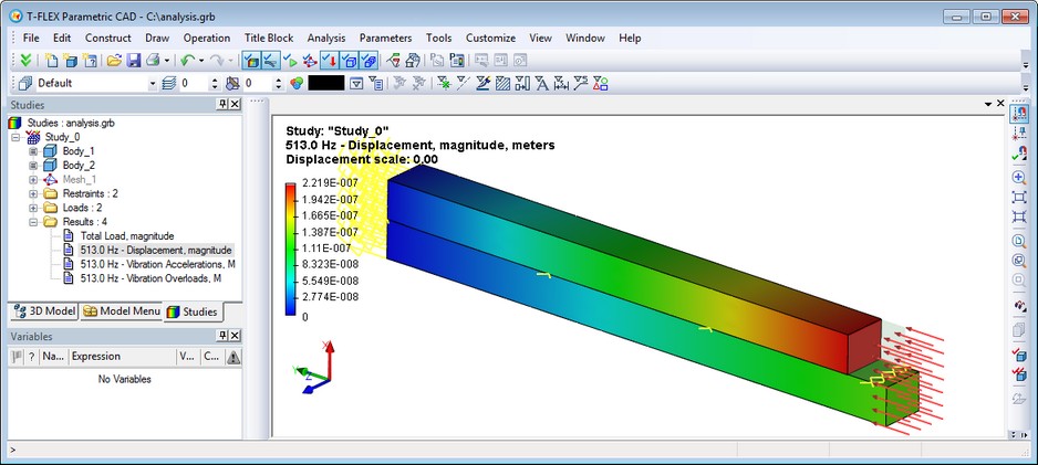
The purpose of forced oscillation analysis is to obtain the system response depending on the frequency of forcing action. The results of the calculation are the amplitudes of displacement, vibration acceleration and vibration overload at the specified frequency. You can view the deformed state of the construction in different phases. According to the results of calculation you may obtain dependencies of amplitudes vibration accelerations from the frequency of the constraining forces, which is important for evaluating system vibration resistance at a given frequency range.
Analysis of forced oscillation is performed in several steps. The sequence of user actions for the preparation and implementation of this type of analysis is very similar to the algorithm of static analysis.
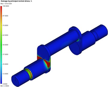
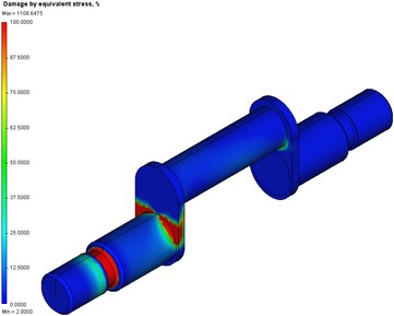
New Study – «Fatigue Analysis»
Another new type of study - "Fatigue Analysis" - allows you to analyze the strength of the material under variable loads.
Before calculating fatigue strength you should first perform static analysis to determine whether the product is exposed to failure under a given load. If the product breaks down with the given static load (safety factor is less than 1), then performing fatigue analysis does not make sense.
Equivalent and principal stresses resulted from static analysis are used as the amplitude of cyclic stresses to calculate the fatigue strength. Fatigue curve must be specified for model material for fatigue analysis. Fatigue curve may be selected from existing curves, or specified by the user.
There are two types of calculations for fatigue studies: single event and multiple events. In single event study system assumes that all loads applied are changed cyclically by the same law - number of cycles and the type of cycling change for all loads are identical. Multiple events study allows to evaluate the impact of several forces with different parameters of cyclic loading. This can be defined as a different number of cycles, and distinct types of changes in cyclic loading.
For cyclic loading the following parameters must be defined: number of cycles; type of loading; the stress correction method, which is set if the stress ratio R is not the same as the ratio of the given fatigue curve; scale effect factor (stress scaling factor).
After calculations of fatigue study user gets 10 results.
●Damage by principal stress (Gest-Mohr hypothesis - the theory of major principal stress);
●Damage by equivalent stress (Huber-Mises-Hencky hypothesis - the distortion energy theory);
●Damage by stress intensity (Tresca-Saint Venant hypothesis - maximum shear stress theory);
|
|
|
Damage by principal stress |
Damage by stress intensity |
Damage by equivalent stress |
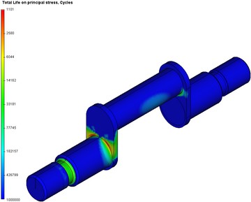
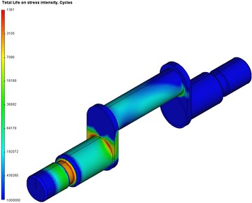
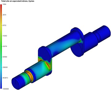
●Total life on principal stress.
●Total life on equivalent stress.
●Total life on stress intensity.
This type of results is available only for single event calculation.
|
|
|
Total life on principal stress |
Total life on stress intensity |
Total life on equivalent stress |
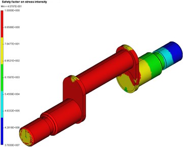
●Safety factor on equivalent stress (Huber-Mises-Hencky hypothesis - the distortion energy theory);
●Safety factor on stress intensity (Tresca-Saint Venant hypothesis - maximum shear stress theory);
●Safety factor on principal stress (Gest-Mohr hypothesis - the theory of major principal stress).
This type of results is available only for single event calculation.
|
|
|
Коэффициент запаса по главным напряжениям |
Коэффициент запаса по интенсивности напряжений |
Коэффициент запаса по эквивалентным напряжениям |
●Biaxiality - the ratio of the smaller alternating principal stress (different from 0) to a larger alternating principal stress:
![]() ,
, ![]() . Biaxiality characterizes the amplitude of the principal stresses at the point and describes the spatial unevenness of distribution in terms of principal stresses at each point of the body. The value of biaxiality equal to 1 corresponds to a constant-stress condition at the point (
. Biaxiality characterizes the amplitude of the principal stresses at the point and describes the spatial unevenness of distribution in terms of principal stresses at each point of the body. The value of biaxiality equal to 1 corresponds to a constant-stress condition at the point ( ![]() ).
).
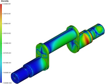
Available only when the fatigue study is defined with one event.
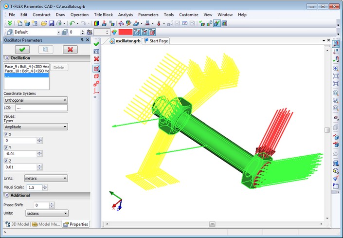
New Type of Load - «Oscillator»
"Oscillator", a new type of load to specify the source of vibrations, was added. It helps to set spatial oscillations with fixation of direction along the axes.
This kind of load can act as full or partial restraint. If the oscillation direction is not fixed, it is considered restrained. Load is applied to faces, edges, vertices of bodies, and may be applied to specific bodies of the assembly model. To indicate the direction of oscillation you may select local coordinate system, and the very direction is indicated by setting checkbox corresponding to the axis of local coordinate system.
The type of kinematic load is selected from the list and can be as follows: the amplitude of points displacement, velocity, acceleration, overload (g). In a separate field you can set phase shift, measured in degrees or radians.
When oscillator load is combined with partial fix for the same model element, directions of oscillations and restraints must be different.
Visually, the oscillator is shown as a wavy arrow indicating the direction of propagation of the oscillations.
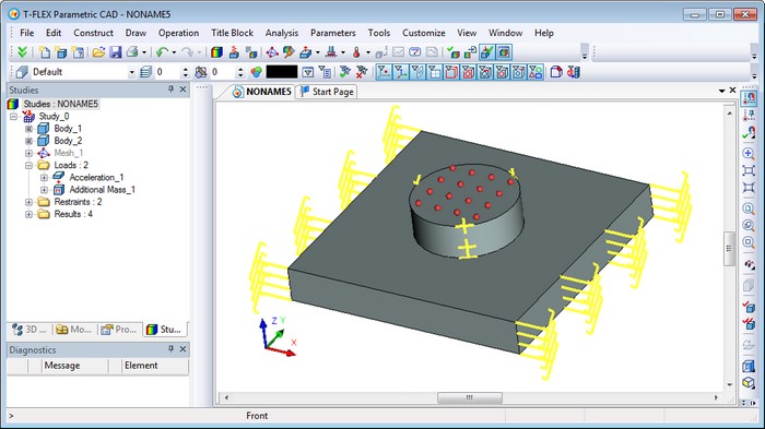
New Type of Load - «Additional Mass»
The new type of load – “Additional Mass” – may be used in the following studies:
●Static analysis;
●Frequencies analysis;
●Forced oscillation.
"Additional Mass" can be applied to the vertices, edges or faces. The range is 0..1е16. Linear acceleration is required for this type of load to be considered in calculations.
Visually, additional mass is displayed as "balls".
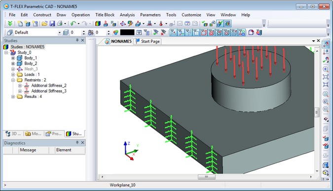
New Type of Restraint - «Additional Stiffness»
The new type of load – “Additional Stiffness” – may be used in the following studies:
●Static analysis;
●Frequencies analysis;
●Forced oscillation.
"Additional Stiffness" restraint can be applied to vertices, edges or faces. Visually it is displayed in the form of zigzag lines on the X, Y, Z components on the outside of the body (faces).
New Command - “Exclude/Include from/in Study”
The new command added to T-FLEX Analysis allows you to control which loads and restraints from the set of created must be considered in the current calculation process.
This command is called from the context menu of the analysis study. Elements excluded from the study are not involved in the calculation.
Sensors
Functionality of sensors was essentially improved. The sensor allows you to display the value of the corresponding result of the study at its position on the model. It can be placed on some particular element of the model geometry - vertex, point on edge or face - or in any 3D node, located either on the surface of the model, or in bulk. It is not possible to place sensor at 3D node that is outside the model. For convenience, the command for creating 3D node was added to automenu of sensor creating/editing command.
In general, the use of sensors does not require recalculation of the study. Sensors can be added after the calculation performed. Sensor readings in the form of the characteristic tags are visible when viewing the corresponding result in the postprocessor window.
Sensors created on curved surfaces may have invalid values (zero readings) without recalculation of the study, as they will be outside of the finite element mesh. Tags of such sensors have red border. To eliminate such situations you need to update the finite element mesh. Rebuilding the mesh will take into account the presence of sensors and new additional mesh points will be created automatically at positions of sensors.
Graphs Templates for Postprocessor
New "Create Graph Template" command was introduced.
Graph template contains an ordered set of sensors for creating graph from their values. The command is not available if the number of sensors in the study is less than two. Sensors and their sequence are specified when creating a graph template.
Graph template is used in "Graph" command.
Graphs is Postprocessor
New command "Graph" allows you to visualize the changes of result for an arbitrary set of sensors specified by "graph template". The command is available from the context menu of the appropriate result (selected by the user) in the presence of at least one "graph template" in the study.
New Options in Finite Element Mesh Generation
New parameters were added to the dialog of finite element mesh generation command: correction of self-intersections, criteria for geometry of the surface and volume finite element meshes, level of refinement for thin volumes.
|
Surface Mesh Proximity (0-4) – option to automatically refine the surface mesh in areas identified as thin volumes. This option is used to improve the shape of the volume elements in the sections, where the mesh size is not optimal. Fix Self-intersections – Option controls correction of self-intersections of the surface mesh. At the end of the surface mesh generation, it will be checked for self-intersections, and any intersections found will be corrected, if possible. Surface and Volume Meshes Metrics Criteria – Options to control criterion for selecting the desired form of the metric for the surface or volume mesh. These options set the form of the metric that is used as a target for various procedures to improve the surface and volume meshes, for example, in optimization procedure: Angle – maximum value of the dihedral angle for triangles and tetrahedra, in degrees. The default value is 145. The value must be in the range 145° ≤ angle <180 °. Symmetry – criterion of equivolume asymmetry. Unitless parameter, which must be in the range from 0 (equilateral triangle, tetrahedron) to 1 (degenerate element). Sides – Criterion for the proportions of sides. Unitless parameter having a range from 1.0 (equilateral) to ∞ (degenerate). The default value is 12.0 for tetrahedra and 6.0 for triangles. |
T-FLEX Open API
T-FLEX Open API functionality was improved. New classes and methods were added.