New Capabilities of T-FLEX CAD Version 14


New Capabilities of T-FLEX CAD Version 14 |
|
This document presents review of new functionalities, capabilities and improvements of T-FLEX CAD version 14. This information is primarily intended for experienced users who have good knowledge of the main system tools. For detailed acquaintance with the system functionalities, please refer to the respective sections of Help or User Manual.
System Performance Optimization
One of the most important parameters of any design system is its performance. When working on T-FLEX CAD 14, developers paid special attention to this factor. Serious improvements have been made in the system’s core, in graphics display subsystem and basic math of 3D transformations. The result has been a significant increase in the rate of models recalculation and visualization, as well as acceleration of operations with assemblies, arrays, and other elements that require significant computing resources. File format underwent serious change. This has resulted in significant reduction of the physical file size (in some models of up to 10 times).
These efforts resulted in the overall performance improvement, especially noticeable when creating large assemblies. Operation is now more comfortable and allows the designer to focus more on the task being solved.
New 3D Graphics Subsystem
New improvements were implemented in T-FLEX CAD 14 to increase performance and visualization quality of 3D graphics output.
New graphics engine uses enhanced algorithms and modern tools that ensure higher productivity of operations, including large three-dimensional models.
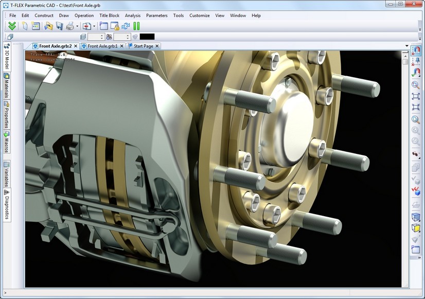
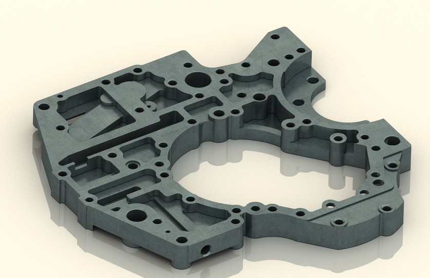
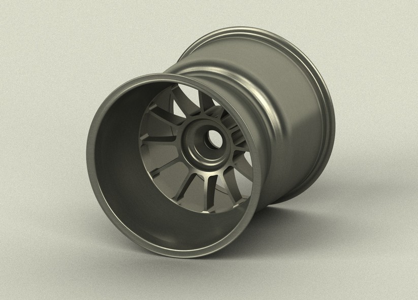
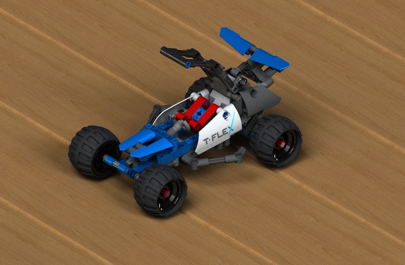
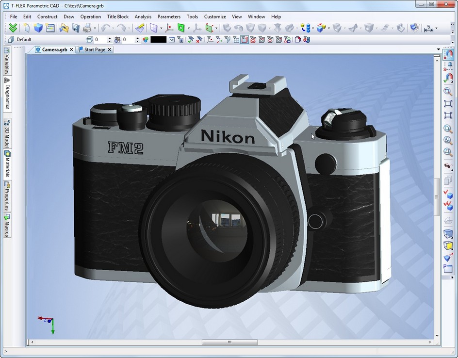
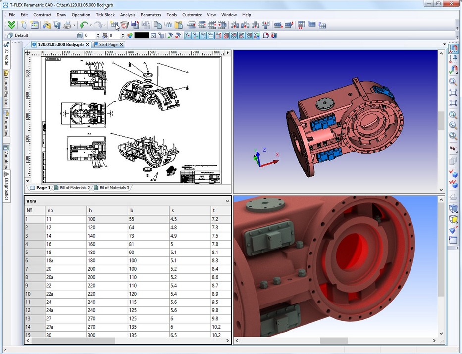
New mechanism for generating photorealistic images based on NVIDIA OptiX technology is designed to generate high quality photorealistic images based on lighting and material properties such as transparency, refractive index, surface properties, etc. The new mechanism allows obtaining photorealistic images directly from T-FLEX CAD 14 environment when working with 3D models providing convenient interface of 3D scene parameters management, control over the quality of result and possibility to print result or save it to a file.
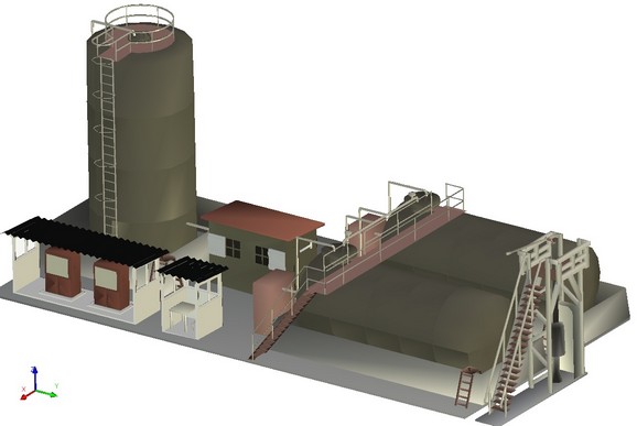
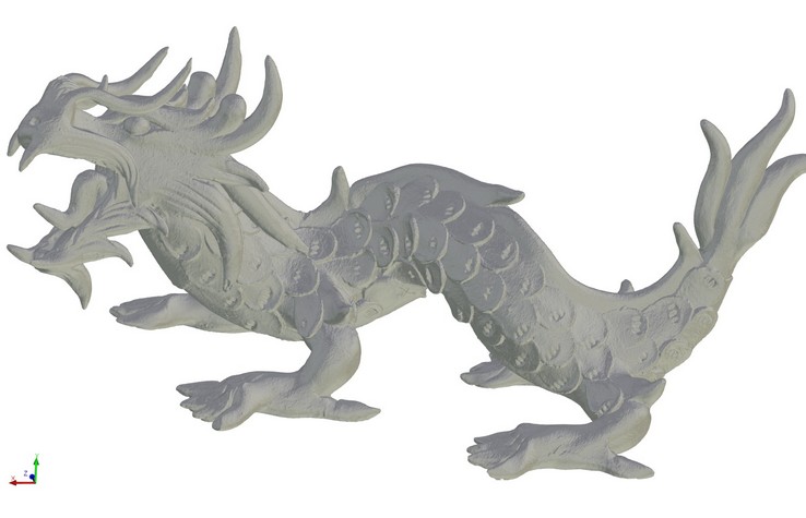
With the new mechanism photorealistic image can be generated not only from the three-dimensional solid models, but also from the imported triangulated 3D models.
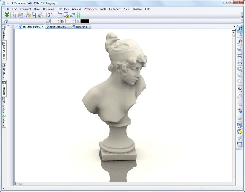
A new type of window was introduced. It contains associative dynamic photorealistic images with interactive update. If you change the model, you can update the image by pressing a button to see changes with the same settings of the scene. In this window, all T-FLEX CAD classic user interface elements are available - main text menu, toolbars, and main toolbar. The model can be rotated with the mouse, as is done in the normal 3D window.
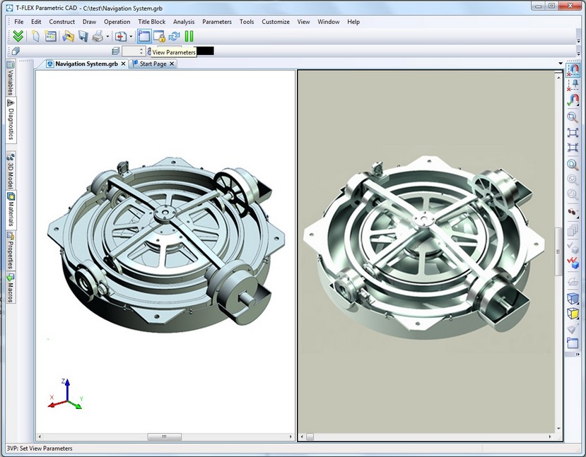
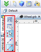
Window with photorealistic image has a special toolbar to work with photorealistic images.
![]()
This toolbar has the following commands:
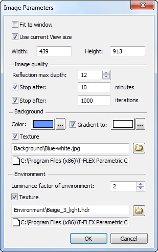
●Set parameters of generated image
●Suspend and resume image generation
●Fix the view direction and zoom. Rotation of the model in this case becomes impossible. Image continues to be generated continuously without interruption. Option is important to prevent occasional restart of image generation that may take long time in complex cases.
●Export photorealistic image files in raster formats.
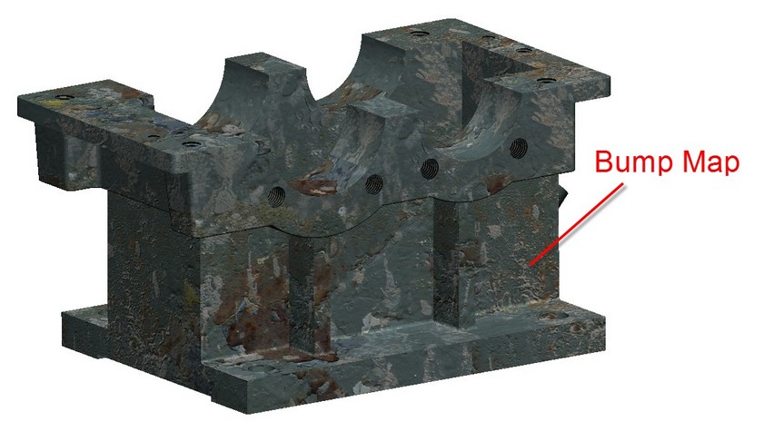
Bump mapping was added to provide more realistic and saturated view of objects surface.
New dialog of 3D graphics parameters was developed. It contains various options and modes that allow users to define optimal settings for their hardware and modeling environment.
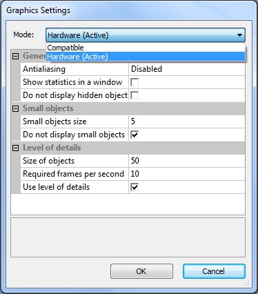
●Option "Do not display hidden objects" was added. This option eliminates recalculation of objects which are currently not visible in the scene, i.e. covered by other objects. This speeds up rendering, especially for large numbers of objects.
●Parameter responsible for managing small objects rendering was added. This option allows improving rendering performance of large assemblies by eliminating the display of small objects.
●Enabling "Do not display small objects" does not allow the system to draw objects with sizes less than the specified value.
●Group of options responsible for detailing objects on screen was added. Now you can select the size of objects that can be drawn, set the optimal rate of 3D models redrawing, as well as simplify the visible geometry depending on the size of objects on the screen.
"Size of objects" parameter allows you to manually set the maximum size of objects in pixels that can be drawn in the form of parallelepipeds, which will reduce the time the image is drawn. Parameter "Required frames per second" allows you to set the optimal model redraw in the 3D scene.
Enabling "Use level of details" option allows simplifying the visible geometry depending on the size of objects on the screen. When required values in frames per second fail to display model, system determines which model part takes the smallest area in the frame. These bodies are drawn in a simplified form of parallelepipeds. Thus, model is simplified until the frame rate becomes higher than required.
Bitmap image defined as file may be used in 3D window as a background.
Using background image in a particular window can be disabled by means of special option in 3D view properties.
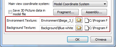
In addition environment texture may be used in 3D window when rendering models.
This mechanism allows surrounding the model with three-dimensional image, which will be reflected in the faces of the model. Thus, the user has the opportunity to form virtual environments for their models. Textures use HDR format.
Functionality for working with 3D scenes was implemented. Scenes provide a visual backdrop behind a model. Scene contains description of color and texture of background, environment texture, position and brightness of light sources. Scene setup may be saved to external file for later use.
You can save scene in the 3D view properties dialog using button "Save scene ...". You can download the scene in the same dialog box by pressing the "Load scene ..." button or by dragging the file to the 3D window from Windows Explorer or other source. System installation includes number of preset scenes that provide high-quality image in 3D window and in the photorealistic view.
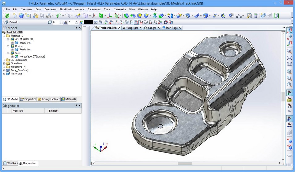
Materials Management
Materials management and material libraries have been substantially redeveloped for improving general operations, materials search, quality of visualization, engineering calculations, integration with T-FLEX DOCs and other systems.
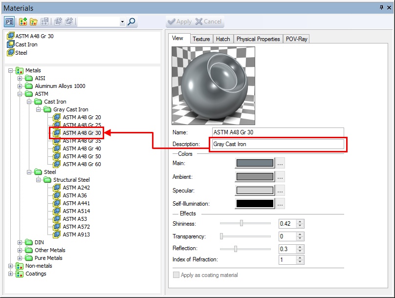
New Dialog of Material Properties
Editor of material properties was completely redesigned and now works in a non-modal floating window. Material editor can now work without an open document.
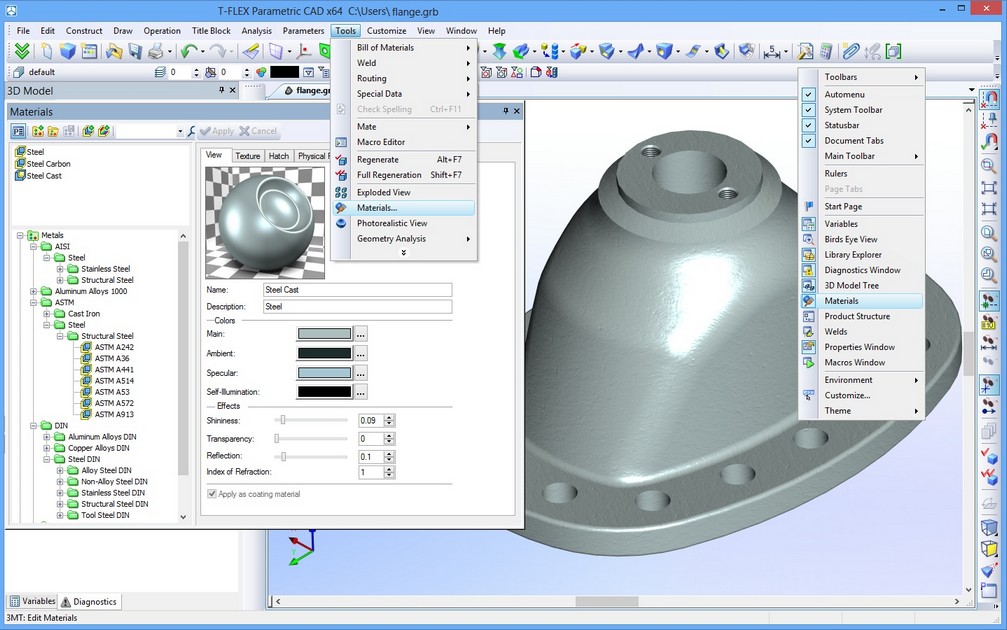
New special window is now used in system’s interface for controlling materials and libraries, allowing to see and edit all the properties of material.
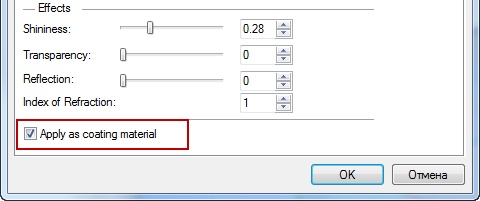
New parameter “Apply as coating material” is introduced for materials that are used only for model appearance and do not contain physical properties.
Materials used in the current model are now displayed in the Model Tree. Using Model Tree context menu you may call “Properties” and “Delete” commands. Also you may see there usage of materials in bodies and operations of the current model.
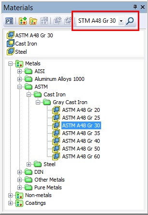
Search option was added to materials dialog toolbar. It allows searching for particular material by its name or part of its name.
Behavior of the material properties window has been changed. Now the properties window appears by double-clicking material in document or library.
New field, “Description”, was added to the properties of material. This field displays the name of folder containing material.
For the model material this field can be edited so you may enter your own description.
When copying material to a library, description will be named by folder name where it is placed.
Creating Material Based on Color
New option was added to material libraries management dialog - «Create color-based material». When it is used selection of color from catalogs of colors will appear on screen.
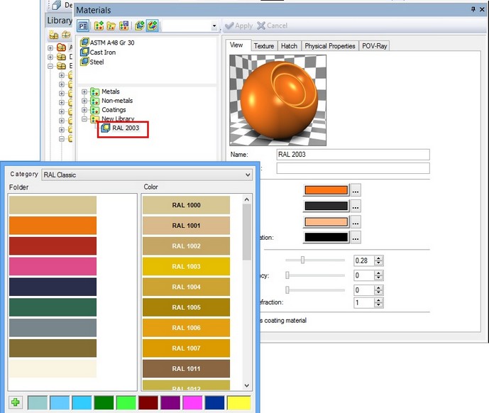
After confirming your selection, new coating material will be created in the current model or library of materials with the appropriate name and properties.
Color catalog contains set of pages (left list) with colors. Each color is defined as RGB components and name.
Besides the color list in the catalog, dialog contains 10 favorite colors, which user can add from the list and have quick direct access to them.
Each color catalog is stored in a separate file with .acb extension. Modification of the catalog colors may be done in text editor or any specialized editor of .acb files.
Applying Materials Using Drag&Drop and Copy/Paste
Materials may be applied by various ways:
●Applying material on bodies and faces is possible now from clipboard using «Copy» and «Paste» commands. «Copy» command may be used in «Materials» window, in model tree for material objects and in materials dataset of T-FLEX DOCs application.
●Using drag&drop. Dragging can be performed from materials window or model tree. Depending on the filter installed in 3D window, material is either applied to a face or a body.
Depending on its type material will be applied as basic or coating material.
These mechanisms are available both within a document and between documents of the same instance of T-FLEX CAD application. They can be used to copy materials from one T-FLEX CAD application instance to another, as well as from T-FLEX DOCs to T-FLEX CAD and back.
Material Properties
New material properties for rendering and photorealistic images were added:
1.«Texture» group. This parameter group is responsible for creating the visual relief of surface material. The essence of the feature is that by adding shadows and highlights we get effect of the surface material relief.
There are three main ways for creating effect of relief surface corresponding to texture type:
●Bump Map. This texture allows to simulate simple bumpy surfaces, flat protrusions or dents.
●Normal Map. This texture like bump map allows to simulate bumps and roughness of the surface. This texture more accurately renders surface relief compared to bump map texture.
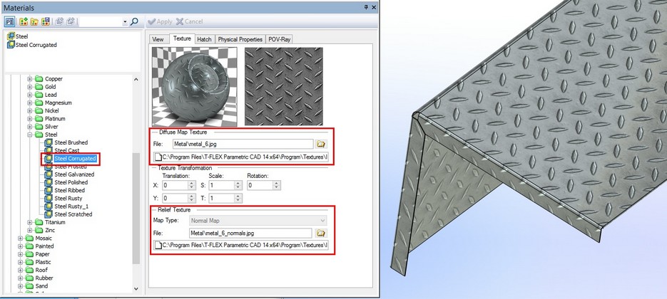
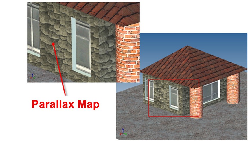
●Parallax Map. If you use this texture surface relief becomes three-dimensional and looks differently from various angles.
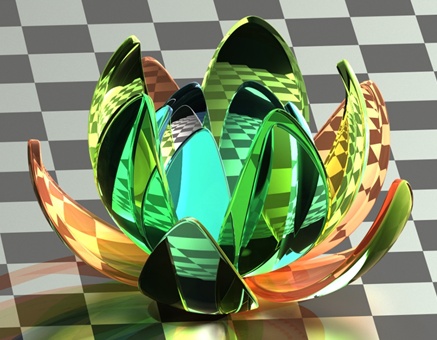
Reflection. This parameter defines the amount of material specular reflection. It is defined as a number ranging from 0 (reflection of surrounding objects will not be considered) to 1 (provides the total reflectivity of the material). In contrast to "Shininess" parameter, which determines how much light is reflected on the surface, this parameter adjusts the reflection of other objects on the surface.
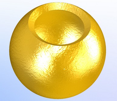
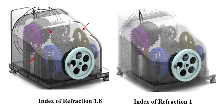
1.Index of Refraction. This parameter characterizes the deflection of light rays as they pass through the transparent material. Using the index of refraction you can set the value of this parameter for a transparent material.
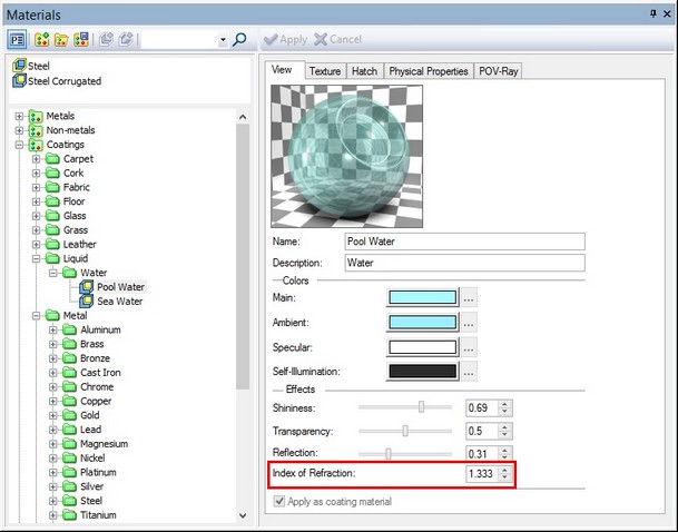
This option is taken into account when generating photorealistic images.
Managing Libraries of Materials
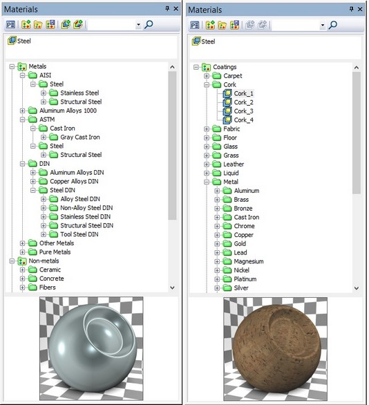
Number of improvements related to managing library materials were made, including the possibility to work with multiple libraries of materials simultaneously. System installation includes new libraries of materials most popular in engineering work. Libraries include materials that meet the requirements of AISI, ASTM and DIN standards.
In addition, system comes with library of coating materials, providing high-quality rendering of products, including the generation of photorealistic images.
For various operations with libraries and materials including structure modifications you may use commands from right button context menu of “Materials” window.
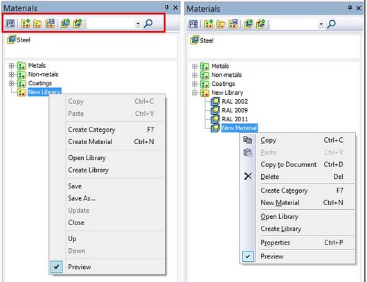
To move materials within a library, from one library to another or to the list of current model materials you can also use drag and drop functionality. To move material within a library from one folder to another or from one library to another, use right mouse button; to copy, use left mouse button.
You can copy separate materials and entire folders with materials, using context menu commands "Copy" and "Paste".
New folders (catalogs) within a library can be created using appropriate context menu command of this library.
Use “Copy to Document” context menu command or left button drag and drop feature to copy materials from a library to the list of materials of the current document.
Preview of material is available in the bottom of materials window as image of a ball or a cube toggled by mouse click.
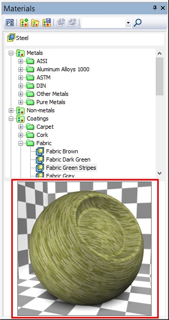
Preview of material allows user to visually estimate material before applying it to objects in 3D scene.
Routing
Functionality for designing communications was expanded with various new objects such as routs, rout styles, compatibility rules and tools for operating with them including support for standards and automatic routing.
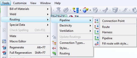
New groups of commands combined as "Routing" are intended for design automation of electrical, ventilation and piping systems in various engineering areas. "Tools | Routing" menu includes relevant sections of various types of applications, “Piping”, "Electricity", "Ventilation" and service commands.
Functionality of commands in the groups described above is configured for certain types of communications. Such grouping ensures compatibility of elements between each other.
Command «Construct | Pipe Path» was renamed to «Construct | Route».
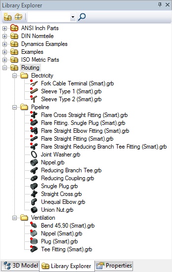
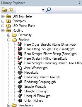
System installation includes libraries for each type of routing, containing various parts that may be used as routing components.
Routing Types
Routing objects may be associated with particular types. These types define behavior of objects in usage as well as rules of compatibility of various objects between each other. For example, type may specify some allowable values of parameters like amperage for electrical components and wires. Mismatch of parameter values will not let incompatible components to be used within the same routing set.
Type allows you to exclude errors in connecting elements together. Type can be assigned to the following objects: pipeline, wire, cable, route, and connector.
Type is selected from the tree structure created in the editor of connection types. If compatibility is set for the base type, the default child types inherit these rules, but you can change or supplement to them.
In the "Routing" menu you may find commands for creating connection points, routes, harnesses, pipelines, as well as command for filling the route with components according to the specified style.
New options were added to the commands of route filling:
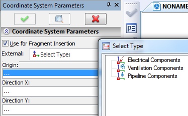
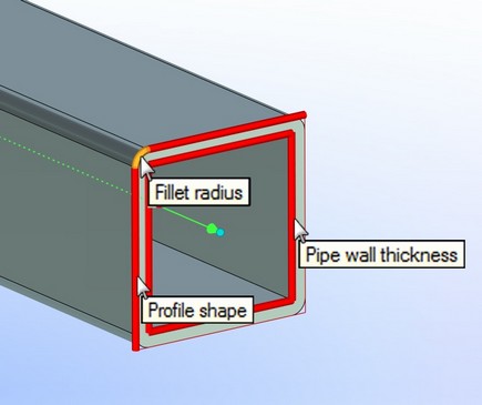
1.Profile type selection – round, rectangular or from the list of standards.
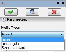
Various parameters may be set depending on the profile type: diameter, wall thickness, width, height, etc. When one of the standards is selected, values for the parameters will be defined from this standard. Profile can be resized using manipulators in the 3D scene. The current value of the edited parameter can be monitored and set in the system toolbar.
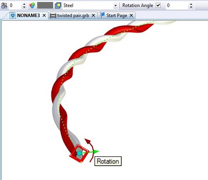
2.Profile orientation. Angle of rotation can be specified for a rectangular profile. Rotation is enabled by setting the flag "Use". Profile orientation (total angle of rotation about the axis directed along the tangent to the path) on the borders of the tube is defined by two parameters: starting and ending angles.

The angle can be changed by using the manipulator. The current value of the variable parameter is displayed in the system toolbar.
3.List of standards. System installation includes list of standards with a set of standard size profile shapes. The list can be expanded by user. Editor of the list of standards can be accessed using automenu option ![]() . The editor provides possibilities to create, delete, copy/paste data. There is an option to save/read file for organization of team work.
. The editor provides possibilities to create, delete, copy/paste data. There is an option to save/read file for organization of team work.
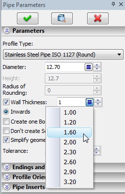
4.Standard can be selected in the properties window when you create segment of a route. If profile type is set to standard, then profile parameters will be supplied with the lists of valid values, which simplify the definition of the correct data.
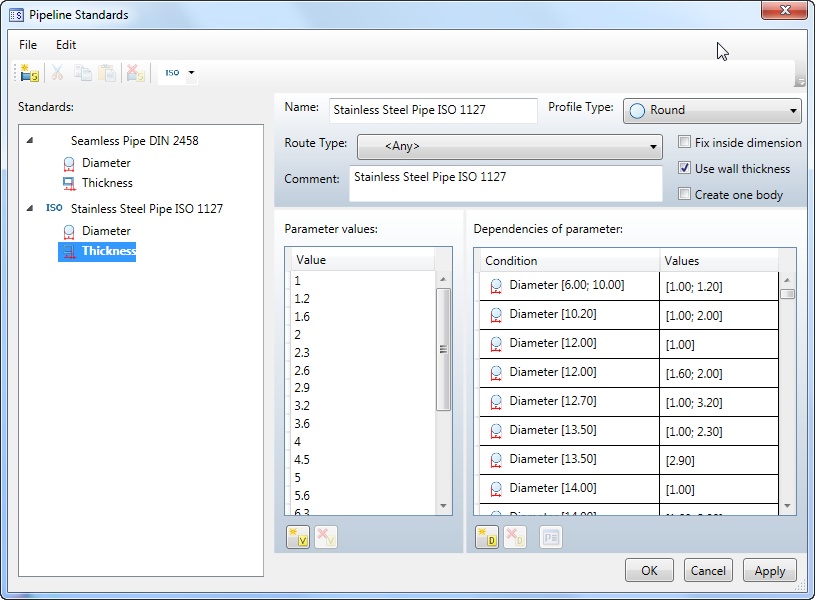
System keeps track of any changes in the data of an existing standard. Routes built using the original version of the standard will not change. In this case, the parameters are stored in the model file, and the dialog of parameters will have additional note in the title "from document".
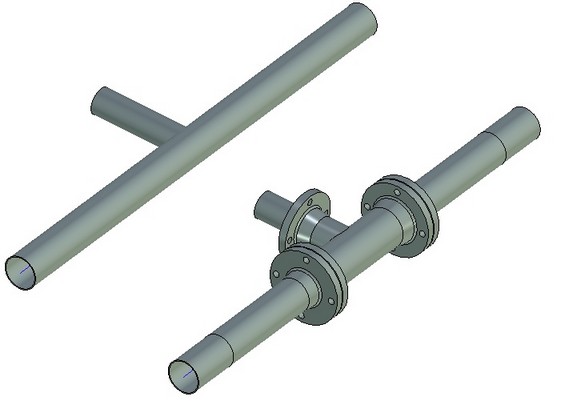
5.Typed ends and connections. When creating a route you can set the types of endings and connections in the model by adding the relevant fragments from library. It may be, for example, external and internal thread, flaring, bevel for welding, etc.
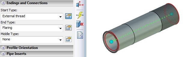
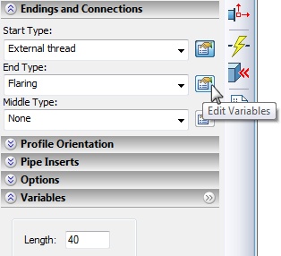
In the model tree such pipeline is presented as a single object, although physically can contain several fragments (start, middle, end). Editing of endings is performed in the routing commands as system treats them as a single object. When you add certain types of endings you may access dialog for editing values of additional fragment variables, such as length. System checks for proper usage and displays diagnostic messages if you cannot perform the operation. Such situation may arise, for example, if the specified length of ending is greater than the route length.
Start, end and middle components are created by certain rules as adaptive fragments in compliance with stipulations for variable names. They are stored in the system configuration libraries Pipe Features and Pipe End Features. The set of such fragments may be supplemented by user.
6.Options for editing start and end positions: ![]() and
and ![]() . These options open «floating» dialog for previewing and editing positions of route ends.
. These options open «floating» dialog for previewing and editing positions of route ends.

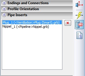
7.Inserts. Pipe insert is designed to modify the pipe. Option ![]() allows you to select a body which will create the pipe cutout. In the model tree body type does not change - pipeline remains the pipeline. Insert in the model tree is presented as a fragment or 3D operation. Insert elements are displayed in the properties window in section "Pipe Inserts". Selected item in the list can be removed.
allows you to select a body which will create the pipe cutout. In the model tree body type does not change - pipeline remains the pipeline. Insert in the model tree is presented as a fragment or 3D operation. Insert elements are displayed in the properties window in section "Pipe Inserts". Selected item in the list can be removed.
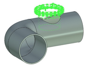
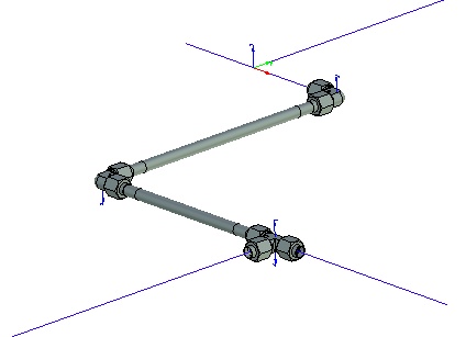
Using Routing Components
General mechanism for routing design was implemented. It provides functionality for setting pipe geometry, insertion of various fasteners and fittings, pipe modification when creating an insert. System installation includes libraries containing various parts that may be used as routing components. They can be differed from other parts by special icon and word “smart” added to the file name. Insertion of such smart fragments may be done by using «drag & drop» mechanism - dragging a fragment from the library window into 3D scene with further selection of route or routing object. Component behavior and its impact on the design depend on its type. When you insert a component, route remains unchanged, and the object is modified in accordance with what component is inserted.
Smart fragments contain embedded micro programs that automate creation and editing of components and provide link between fragment variables and routing parameters. Insertion of smart fragment allows not only to adjust fragment for the current design, but also to perform the following actions:
●Change pipeline diameter.
●Split pipeline into segments.
●Create endings that correspond to inserted fragment.
Set of components in the library can be extended by user.
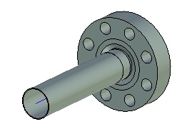
At the moment the following types of smart fragments are available:
cap, double bend, nipple (adapter from tube to flexible hose) |
|
pipe angle |
|
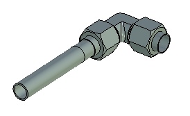
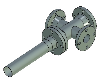
pipe tee |
|
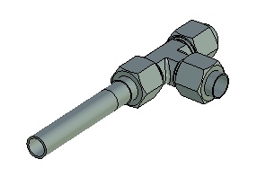
pipe cross |
|
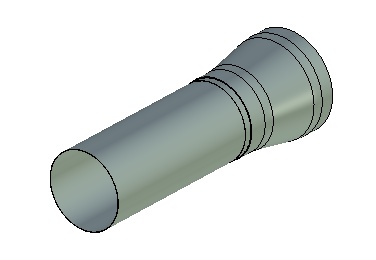
adapter, sleeve, nut, valve, reducer |
|
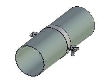
clamp |
|
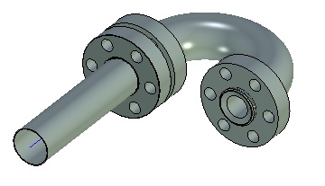
terminal pipe angle |
|
pipe insert |
|
Each fitting type has its own characteristics for creation and use, described in more detail in the documentation.
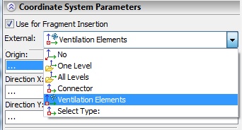
Connection Points
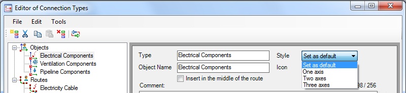
Mechanism that provides automation of routing components connection with each other was developed. For this purpose, new types of connectors called connection points were introduced. They represent local coordinate system (LCS) with certain types. When added to a typed model element, system checks whether a given point can be used for fixing component ensuring that objects have compatible types. Appearance in the 3D scene, icon in the model tree and functionality of connections point can be different depending on the object type and is defined by style. Style can be assigned in "Connection Types" command and determines which axis of connector coordinate system to be used when fixing - one, two or three axes.
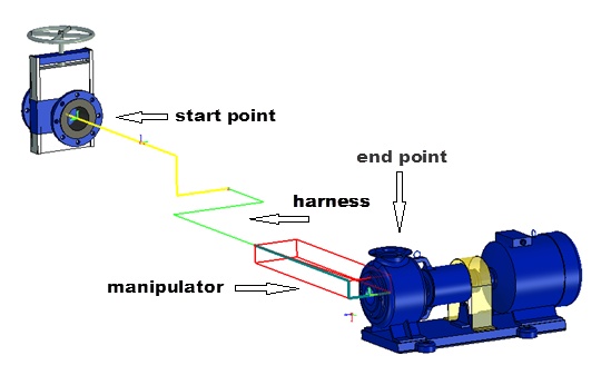
Harness
To merge sets of routing components, following the same route segments system uses the concept of "harness". Harness is used for automated routing when multiple routes pass through the common path. Harness can integrate a variety of routes or other harnesses.
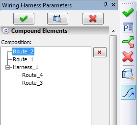
To create a harness you need to build routes that eventually will be combined into harnesses. Prerequisite is the existence of at least one point of intersection of the two adjacent segments.
Editor of Connection Types
Special editor of connection types allows to describe compatibility rules for various types of routing. It assists you in assigning valid correspondence between routes and components and between different types of routes. The structure of the tree and description of the types are contained in the file ConnectorType.xml. It is possible to save/read this file when organizing team work.
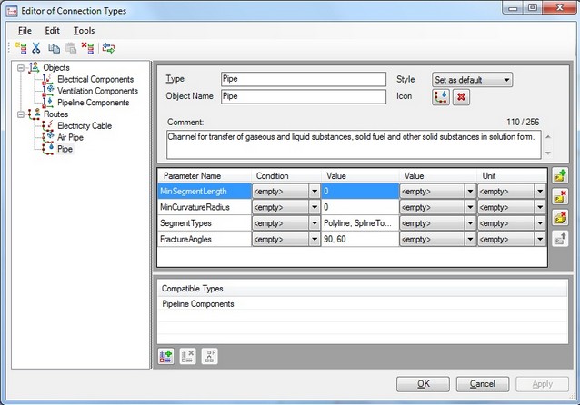
Besides the lists of compatible routes and types you can specify a set of parameters for each type of connections. For parameter you can set condition (equal, greater, less, etc.), value, and name of the units. When connecting routing components system searches for the same parameters and compares conditions set for them. If conditions contradict each other, connection is impossible. Lists of values for the columns "Parameter" and "Unit" are defined in the "Editor of Physical Parameters".
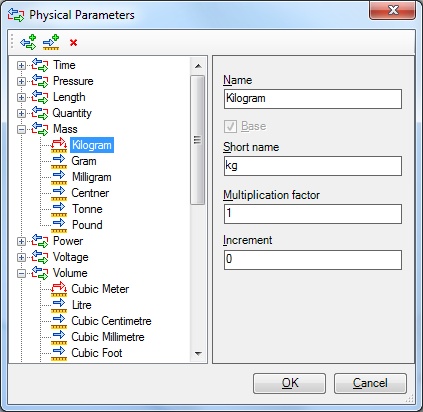
Editor of connection types includes several accessory tools:
●«Editor of Physical Parameters» displays the internal dataset of physical parameters. For each variable, there is a list of units with the name and short name. Flag "Basic" sets the default measurement unit. For other units of measurement scale factor from the base unit is specified. List of variables and units of measurement may be edited.
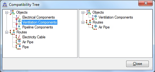
●«Compatibility Tree» - visually displays the created structure of compatibility rules. For selected item system shows all objects compatible with it.
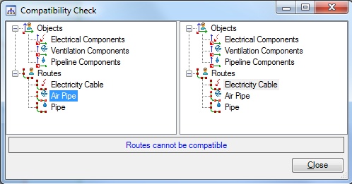
●«Compatibility Check» - allows you to check for compatibility any pair of objects and routes.
Routing Styles
Special editor of styles was developed to automatically fill routes with components corresponding to a particular purpose or standard. Style contains set of rules for filling routes and set of components and fittings, designated for insertion into specific sections of the route. Description of styles is contained in the file PipeStyle.xml. Typically, styles meet the standards that are commonly used in routing design. For example, parts of the pipeline often must meet certain requirements for length and diameter of the segment; in addition, these items must contain fittings made of certain materials.
With the editor you can view, add, modify, and delete styles. You can import and export definitions of styles to the editor in XML file format organizing team work. You can change any of the default styles, or use them as a basis for creating new custom styles. Custom styles can be created from the empty style.
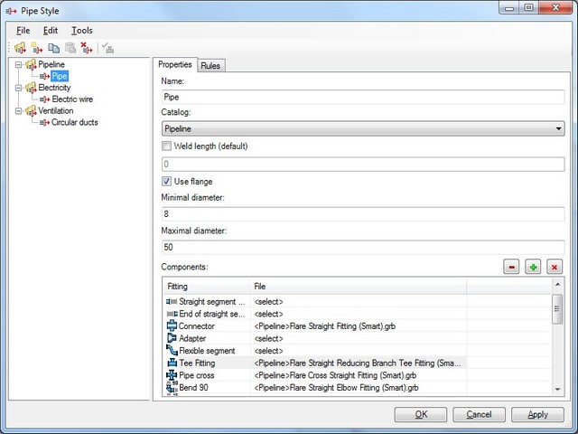
Each style is a set of components – fittings that will be used to fill the route – start/end of the straight segment, bended pipe, etc. Each component can be assigned to a specific file from the library. When filling out route using the style, fittings are automatically inserted into appropriate places of the route. Style also defines allowable ranges of diameter, length of pipe segment, and other parameters.
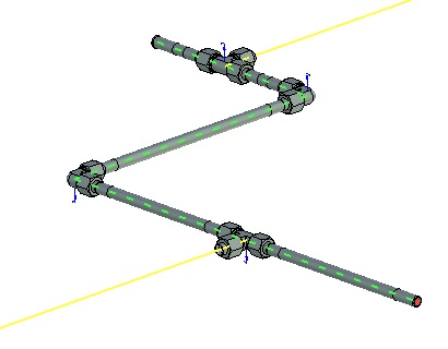
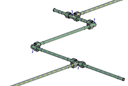
Fill Route by Style
«Fill Route by Style» command is available for all types of routing (Pipeline, Electricity, Ventilation). The command allows to select and fill the main and alternative routes (branches), performs validation of specified values.
Limit points ![]() and
and ![]() allow to fill and clear route in the specified interval.
allow to fill and clear route in the specified interval.
Auto-routing
«Auto-routing» command performs automated laying of route from the original to the target point. To create path for the middle section of the route you may also use harness.
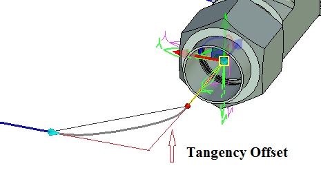
The following parameters are available in auto-routing:
●Tangency Offset – sets the distance that segment of the route offsets from the point of intersection with another segment to build smooth conjugation between them.
●Rounding Radius (only for «Polyline» routes) – sets rounding radius at route bends.
●Route Type: polyline, spline through points, spline by polyline – can be set separately for each section of the route.
●Color.
Auto-routing is performed in several steps, each of which results with a route segment. Segment is laid along the edges of the manipulator-parallelogram or rectangle. User can change the size and composition of the involved edges.
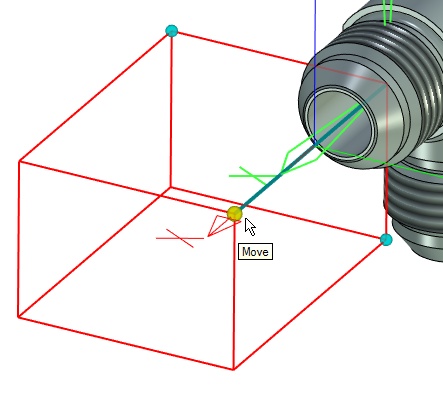
Transition to the next/previous step is performed using automenu options ![]() and
and ![]() . After creation, the route may be edited "manually" with standard editing tools for routes: you can change the types of segments, radii, etc.
. After creation, the route may be edited "manually" with standard editing tools for routes: you can change the types of segments, radii, etc.
Product Structure Management
The mechanism of product structure management was developed. This new mechanism is used to create, view and change the product structure. It allows you to create a single universal structure consisting of all the components that are used in a variety of designs. Depending on the selected conditions the structure may be transformed to any given product variant. Product structure is now used for generating BOM tables. New mechanism allows:
●Parallel control of different product structures.
●Add model objects of any type to product structure.
●Manage the inclusion/exclusion of objects to/from the product structure without removing them.
●Configure parameters that are selected in various product structures for different types of objects (variables, model properties, object attributes, etc.).
●Manage the product structure of any type using special window that displays the structure. Depending on the product structure type, window can have different columns that display object parameters of the structure.
●Configure rules for dealing with different types of product structure.
Designed mechanism provides the ability to display the product structure as a hierarchy if necessary. In particular, it is required if assembly is composed of sub-assemblies and there is need in displaying the structure of sub-assemblies at any level.
Control mechanism is available through OpenAPI to enter data about a product structure, to generate reports, for data exchange with other systems.
Managing Product Structure Types
Type of product structure is identified by a name, for example, "Design Structure." Settings of the type can be stored in an external file and duplicated in the model file, in which this type is used. Thus all settings are stored in the assembly model, and, if necessary, can be saved to an external file.
List of available product structures is formed from a set of files with the settings included in the installation. When you specify some type of product structure, all settings are copied and stored in the assembly file.
«Product Structure» Window
Product Structure management is performed in a special window. It remains on screen for all documents, can be floating or attached to the main window borders. This window also supersedes the former command “Bill of Materials | Data”.
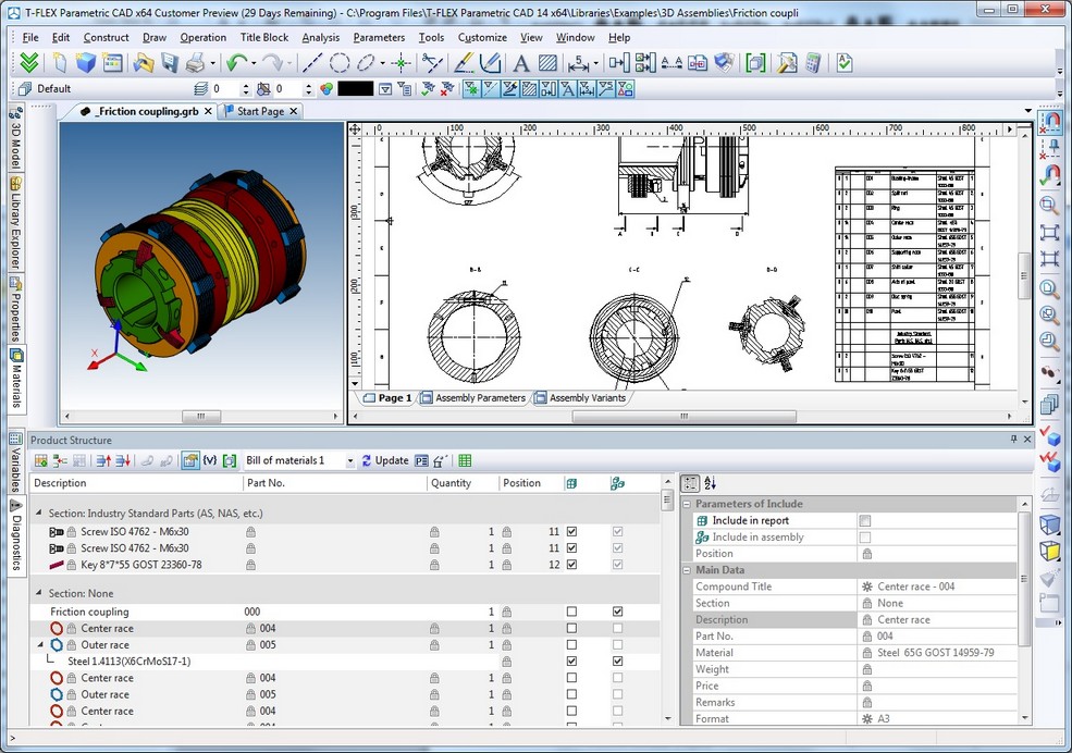
The upper part of the window contains command toolbar and list of available product structures stored in the current document or in external files with settings for custom product structures. Types available in the current document are marked in bold.
Context menu of the list header has commands to show/hide columns, sort and group elements of the product structure.
Editing Types of Product Structure
«Product Structure Types» dialog allows you to set rules for dealing with different types of product structure, namely:
●Terms of automatic inclusion of model objects in particular product structure when creating these objects, and when you create this type of product structure in a document.
●Settings of presentation for this type of product structure in corresponding window. Settings include: composition of columns, grouping rules, sorting rules, the ability to display hierarchy of product structures.
●List of report templates and settings for them for this type of product structure.
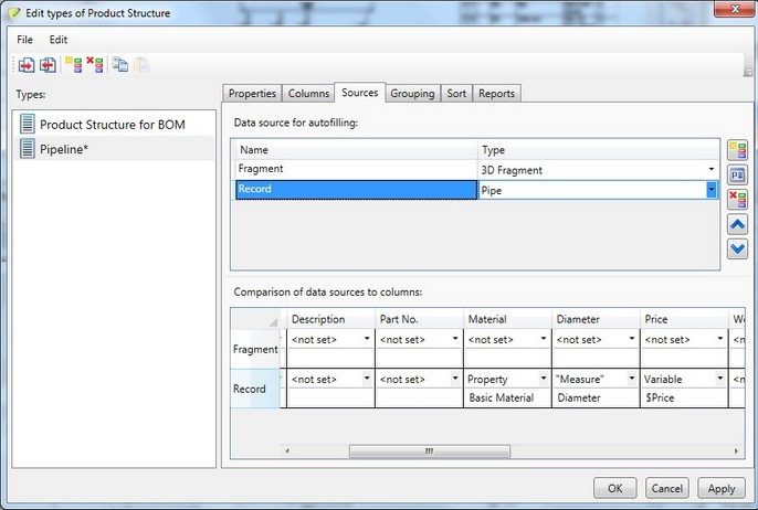
«Product Structure Types» window contains the following data:
●Name. Identifies inclusion of objects into the product structure.
●Parameters. List of parameters which may be filled for product structure elements. For each parameter you can set the rules for getting them from the source object.
●Elements. This is the list of model elements types, which are automatically included in the product structure. For each of the elements you can specify conditions of inclusion. For example, «Weld length» > 0.
●Default Properties. This set of options specifies which columns, in what order, with what sorting and grouping conditions will be displayed in the product structure window.
●Reports. Settings for report generator for this type of product structure. Reports can present the “classic” T-FLEX CAD BOM generators or custom generators implemented using Open API that can be connected to this product structure to generate specialized reports.
The dialog has "Save ..." and "Load ..." commands. These commands allow you to export the settings to description file or import them from file.
Changes in 3D Modeling Commands
Transformations
«Move/Rotate» command was substantially enhanced.
●The command uses new dialog to define transformations.
●You can create new transformations using the context menu or hot keys.
●Possibility to create transformations for multiple objects.
●Transformations of selected objects can now be specified in coordinate system of each member of the group, or in the global coordinate system.
●Possibility to create groups of transformations.
●The command now supports associative fixing, providing positioning relative to other model objects.
●Possibility to quickly edit transformations for operations and construction elements.
●Scaling of objects can now be carried out with the help of bounding box that surrounds selected object in the 3D window.
New «Rib» Operation
Command is used to create ribs on solid bodies. Ribs may be based on one or more contours.
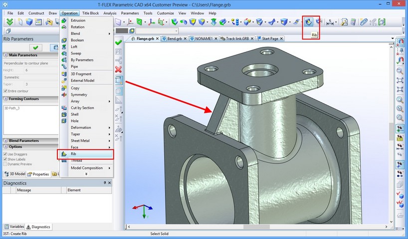
To create a rib you have to select original body, contours, rib thickness and thickness direction.
The result of operation is solid body generated by Boolean operation-union between created rib and the original body.
Additionally, the command allows to set the draft angle, blend radius of edges, blend radius of intersections of edges with the original body.
Boolean Operation
Now some 3D commands that create objects using Boolean operation option allow you to preview the result considering this Boolean operation. If Boolean operation does not affect the model, then the preview will show the result produced by the operation.
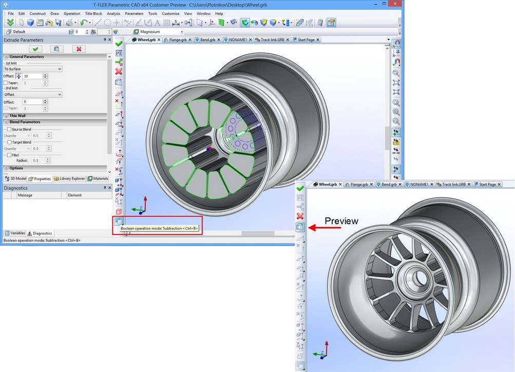
In addition there is a new option to automatically use Boolean operations in 3D commands - Smart mode. When enabled, the type of Boolean operation is selected automatically depending on the geometric context.
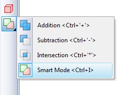
When the newly created body and body selected for Boolean have intersection of volume or new body lies entirely within the selected body, type of Boolean operation will be set to subtraction. When the new body touches the selected body, type of Boolean will be set to addition.
3D Sections
3D sections command now allows fixing to LCS for various types of sections – by plane, by corner, by octant, by parallelepiped.
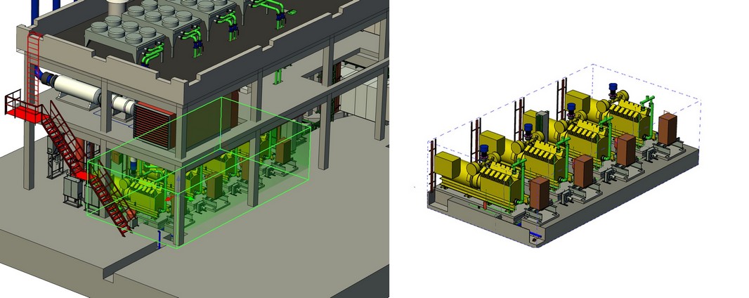
3D sections command has new option for creating sections defined by parallelepiped. Such section cuts off all that is out of the box (parallelepiped). It is defined by two points and coordinate system. Special manipulator is used in this case.
This option allows you to conveniently clip parts in the model, for example, providing the ability to edit the assembly model within a closed space (housing or room).
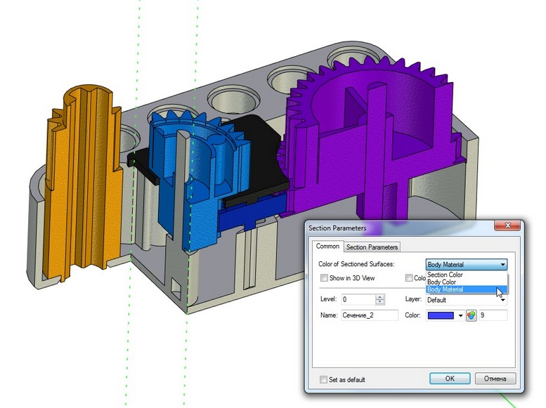
New option was added to section properties - «Color of sectioned surfaces» with values «Section Color», «Body Color», «Section Material».
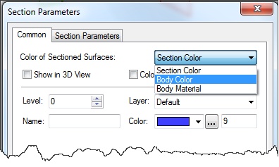
Now it is possible to get different colors when sectioning multicolor assemblies. If parameter value is set to "Body Material", the visual properties of material including texture will be used.
3D Manipulators
There are now new cursors at manipulator elements, which indicate the presence of the element context menu. When one of the manipulator elements is selected, you may access context menu with the following commands:
●translation along axis;
●translation in plane;
●rotation around three axes;
●translation along three axes.
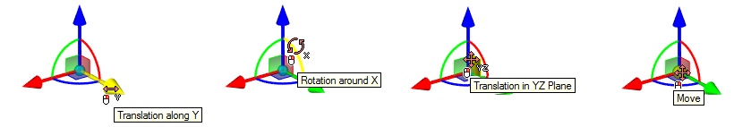
As part of the manipulator, new active elements were added to set transformation in two planes simultaneously.
Manipulators of this type are used in "Move/Rotate» command for three-dimensional operations and constructions. Such graphic manipulators allow you to create and edit transformations more clearly and intuitively.
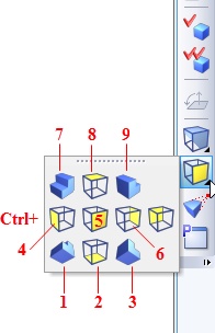
Managing View Point in 3D Window Using Keyboard
In 3D window it is now possible to set the view point using keys on the keyboard - Ctrl + Numpad <Digit>. The digits are used in accordance with the location of the buttons on the keyboard:
2D Projections
2D projections were optimized. In many cases calculation time and memory usage were reduced.
For selected section views new option “From 3D section properties” was added to "Apply to" parameter.
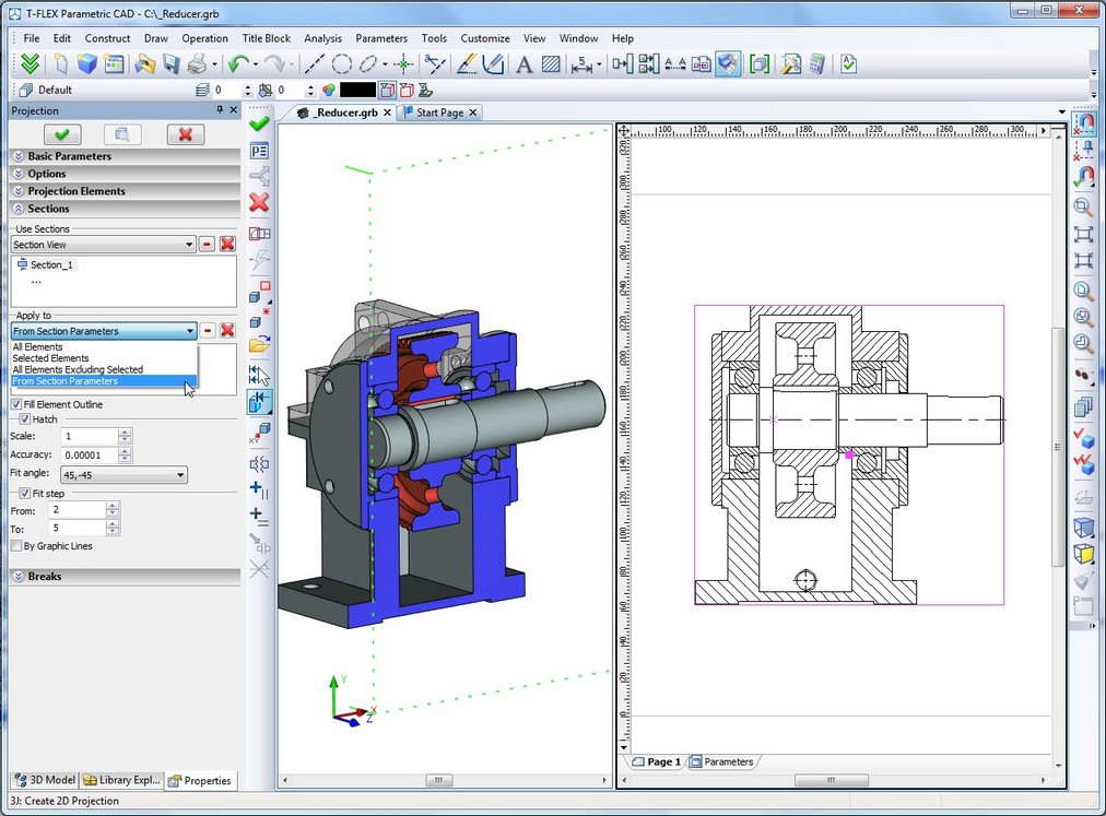
When “From 3D section properties” option is used, rules of applying section are taken from appropriate 3D section properties.
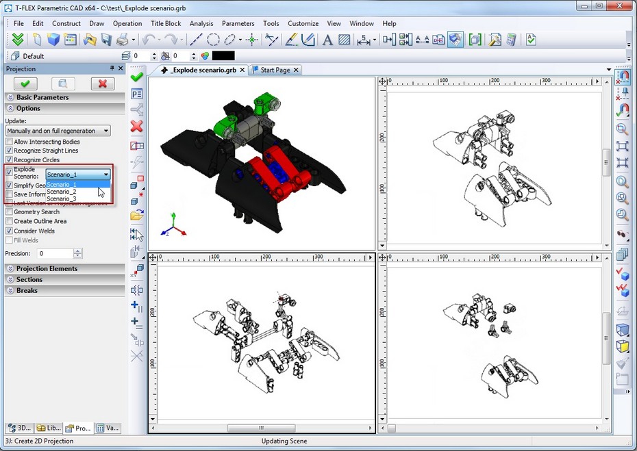
New option for selecting explode scenario was added to 2D projections. This option creates projection of dismantled model according to the specified explode scenario. If there is no scenario, the option will be disabled.
«Holes» command
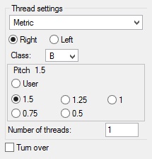
Several modifications were made for the threaded holes dialog:
●User-defined thread pitch value.
●Set of steps for each diameter is now displayed not as a list, but a set of switches. This solution allows you to retain parameterization of holes using variables as a value for diameter.
●Database of pitches was updated
Assemblies
Link Between Fragment Variables and Fixing Points
The mechanism of linking values of fragment external variables when inserted into the assembly was enhanced. In the properties of variables "Assembly Variable" field was replaced with the list of choices that define method of connecting value of a variable with objects of assembly. Now, besides the link to assembly variable you can set values of variable to "Distance between points 1 and 2", "Distance between points 2 and 3", "Distance between points 1 and 3". Last two items are valid for use only in 3D assemblies, which uses three fixing points for locating the fragment.
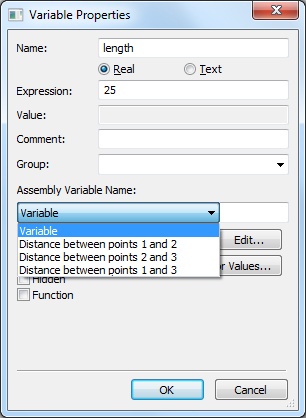
Setting link of external variable this way means that when fragment is inserted in the assembly, variable "length" (in this example) will automatically receive the value of the distance between the first and second fixing points of the fragment. This applies to both 2D fragments inserted by fixing vector and to 3D fragments. In the case of inserting by single point and angle, the value of variable "length" will not change.
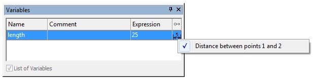
In case of inserting such fragment into the assembly, variable editor in the last column displays the corresponding icon. If desired, this link can be canceled by clicking this icon and removing the appropriate option from the context menu. After cancellation the link with the distance between the fixing points, the value of the variable "length" can be changed arbitrarily.
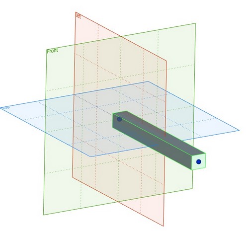
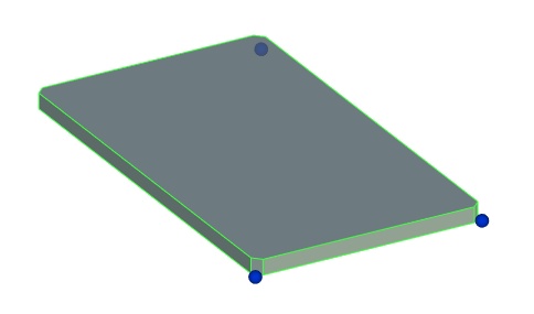
Fixing 3D Fragment by Points
For models that you plan to use as 3D fragments a new mode of inserting/editing was introduced. New mode "By Points" can be set in the dialog of "Status/3D/Fragment ..." command.
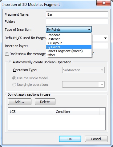
If you set this option, the command of inserting and editing 3D fragment enters special mode of insertion by points. In this mode, user is asked to explicitly select the three points that define the coordinate system origin, the point of X-axis direction and the point of Y-axis direction. The target coordinate system of fragment will not be selected or created in this case. This method of inserting 3D fragments is convenient when fixing structural objects that are defined by their length (or length and width). This may be the beam boards, beams, panels and other structural members. In combination with the possibility to set link between external variables of fragment and coordinates of fixing points, this is a convenient way to operate with metal structures, wooden structures, elements of furniture, etc.
When selecting this type of fragments in the assembly the fixing points are marked as "Point 1", "Point 2", and «Point 3". In this case, when you click at that such, system switches to mode of its redefinition making editing fragments inserted in such a way transparent and user-friendly.
Example of editing fragment "Beam":
Example of editing fragment "Panel":
Layouts
«3D Fragment» command was enhanced: new mode was added for manipulation of 3D fragments created from 2D fragments on workplanes –«Layout Mode». This mode links location of 2D and 3D fragments to each other allowing synchronous transformation of both 2D and 3D assemblies when using manipulators.
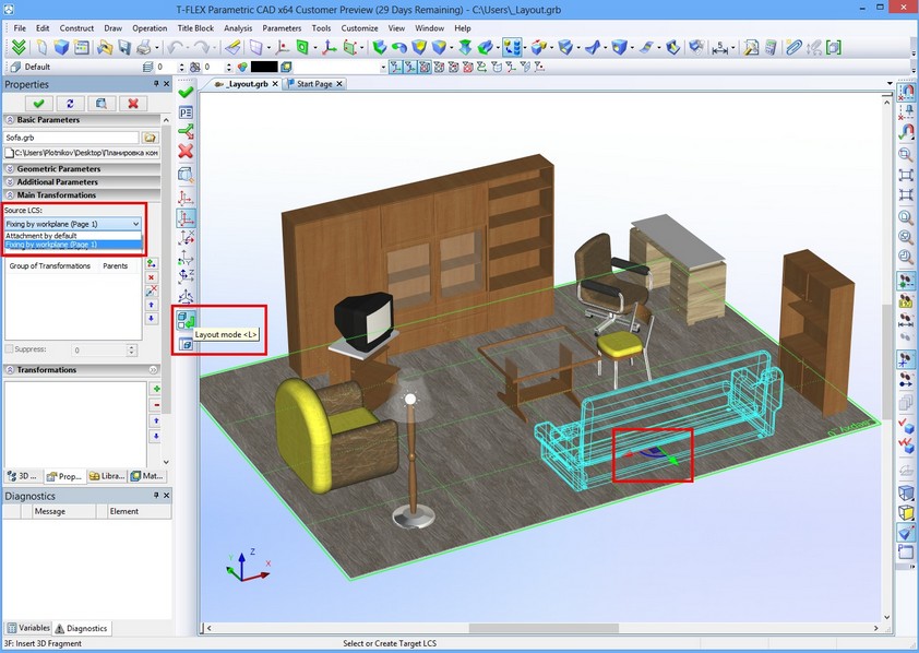
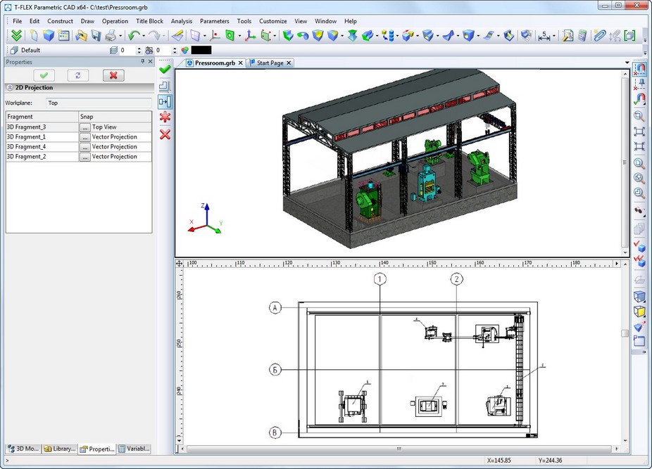
Functionality of inserting fragments as layout was extended. It is now possible to insert 2D fragments that present projection of corresponding 3D fragment. This mechanism of operating with assemblies is useful when designing plans to deploy industrial equipment. It helps you to create drawings of floor plans, plans of rooms, etc.
To create a 2D fragment as projection of the existing 3D fragment you have first to specify workplane when creating a 2D fragment. This workplane helps to position future 2D fragment correctly. Then after selecting 3D fragment that will be used as source for the new 2D fragment you need to define the type of presentation for this 2D fragment. This may be done in «2D Projection» dialog where you can chose either type of projection or fixing vector associated with some predesigned 2D drawing. In case of fixing vector it must follow condition of correspondence to the workplane selected on the first step. In case of projection it will correspond to direction defined by the workplane. As result you will get the 2D fragment that will match source 3D fragment. Location of both fragments (2D and 3D) will be interdependent.
Managing Exploded Views
New mechanism to solve different tasks for exploded assembly views was developed. It provides possibilities to develop and play dismantling scenarios, conduct "virtual tours", demonstrate operation of mechanisms, generate drawings and diagrams of disassembled products, generate demos, visualize the assembly processes.
New command "Exploded View Scenario" is intended to create and edit scenarios of exploded views. Exploded view presents assembly in dismantled way that allows to see assembly components separately. Exploded mode is also convenient to illustrate how the parts and subassemblies are connected and interact. Exploded mode is also helpful for axonometric drawings of assembly model. To create exploded view you must specify trajectories and movement for assembly components.
New type of object was introduced - "Scenario". This object contains sequence of transformations applied to model objects. When applying scenario to the model objects, these objects are moved to predetermined positions either gradually or instantaneously, depending on the mode of scenario. The model may be created with several scenarios. By default, one of them is selected as "active", and actions will made using this scenario.
Scenario can be used when you run the "Exploded View" command, when creating projections, when recording video.
Each scenario is given a name which can be edited. Scenario contains the steps consisting of actions. Every action is an elementary displacement or rotation of one or more parts in the global or local coordinate system.
Command "Exploded View Scenario" is used to create new or edit existing scenarios for exploded view.
Every action has a single or group of objects and chain of transformations for them. As coordinate system of transformation chain you may use either explicitly defined LCS or the first object of the group. For one assembly model you can create several disassembly scenarios. It is possible to use bodies, cameras, lights as objects of scenario. You can also use scenarios of fragments-subassemblies within the overall scenario.
The command supports groups of transformations. Transformations for group objects may be applied independently for each object in accordance with their own coordinate systems or to the group as a whole.
The command allows to control the type and speed of scenario playback. Playing of steps is sequential, one after another; actions within a step are played concurrently.
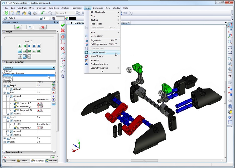
Exploded view may be controlled using the toolbar. Now you can control the visibility of bodies at every step and visibility of the disassembly trajectory. Animation mode supports forward and rotational motion mode, i.e. rotation animation can be done with angles greater than 360° to simulate unscrewing. You can also choose the explode scenario for usage in 2D projections.
New set of icons was added to the main toolbar «Explode Animation».

Toolbar is activated automatically when you run the "Exploded View" command. The controls on this toolbar allow you to perform the following steps:
●Selection of the active scenario. All commands are run with this scenario
●Enable/disable exploded view mode
●Stop the animation of applying scenario
●Suspend/resume animation of applying scenario
●Change scenario stage. This is implemented with “slider” control.
●Enter dismantling management command
●Export dismantling scenario to a file. Currently it is possible to use VRML format.
●Record video based on the scenario
●Show/Hide trajectories of object movement.
Creating Layer when Inserting Fragments
If fragment document has option «Insert on layer», and there is no such layer in assembly then layer will be created automatically.
Reference Dimensions for 2D Fragments
Command «Customize|Status|Preferences|Fragment...» now has «Create dimensions in assembly» option with values «No», «Manually», «Automatically».
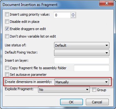
This option creates new dimensions in assembly that replace dimensions existing in fragment being inserted.
Creation of such reference dimensions provides possibility to edit them, as well as to correctly display them regardless of any angle of rotation of the fragment (in the case of insertion by fixing vector).
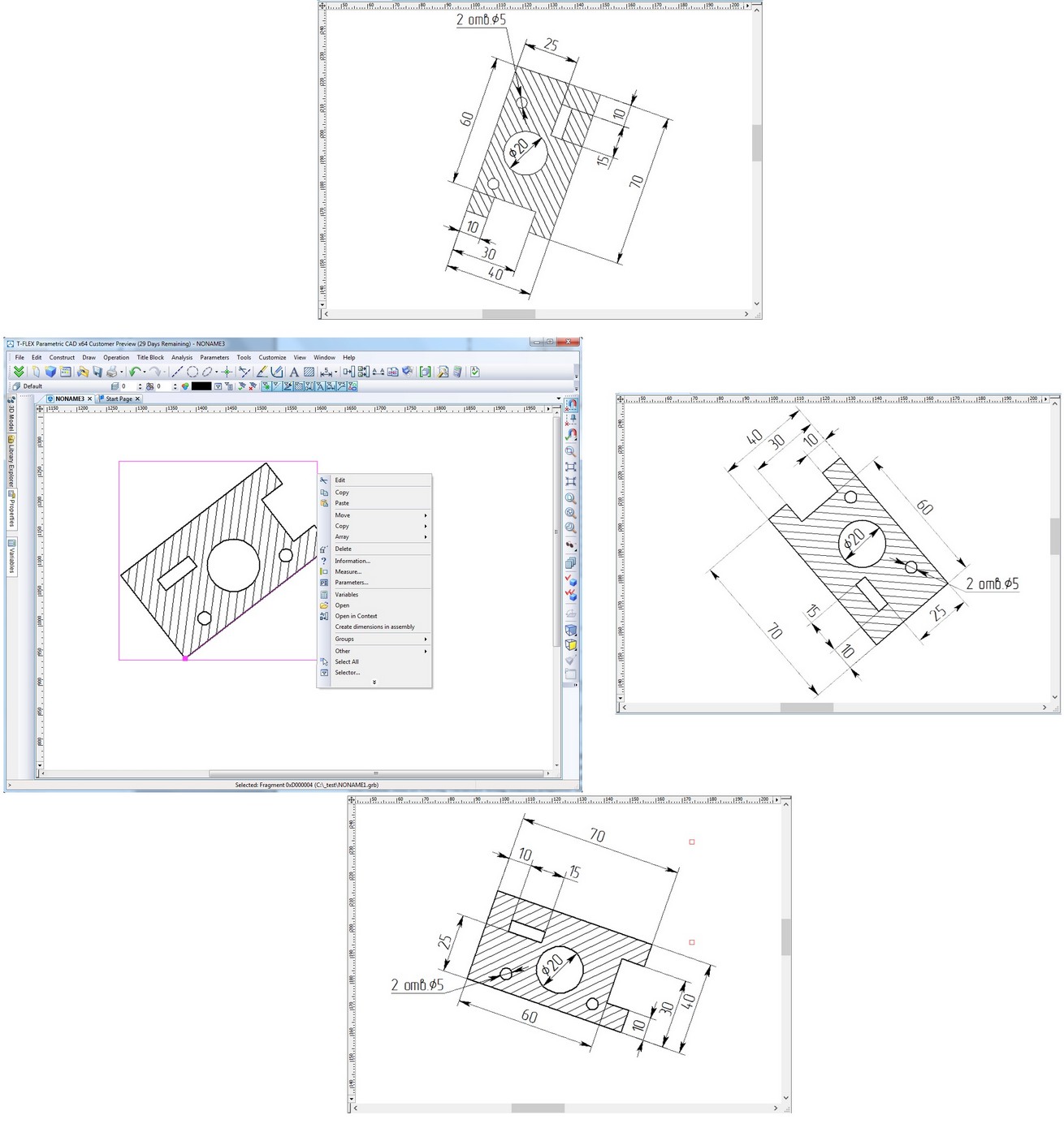
In addition, if dimension within the fragment document is a controlling dimension (i.e. nominal size is set by an external variable), it remains controlling when transferred to the assembly. Thus the command of changing the nominal of dimension will transparently change corresponding external variables of fragment. This is a convenient tool of editing variables using controlling fragment dimensions.
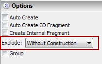
Exploding Fragment on Insertion
Command «Customize|Status|Preferences|Fragment...» allows to set option of automatic 2D fragment exploding after insertion in assembly.
Option may be set to one of the following values «No», «Without Construction», «With Construction».
In addition, a new option "Group" provides the ability to automatically create groups when exploding fragment. When using this option in the command of 2D fragment insertion, after the confirmation of creation, elements created after fragment exploding will be united in group.
Corresponding parameters were also added to «Options» section of 2D fragment command.
Mates
●Mechanism of mates was enhanced:
●Calculations productivity was increased and interface responsiveness during simulation was improved.
●Only movable bodies are now highlighted in the command of moving mated bodies.
●A series of improvements related to the accuracy of calculation of specific types of mates (degrees of freedom of the fragments, axes alignment) were made.
●“Inertial motion” mode was added in "Move Mated Components" command. If you use it and release the mouse, movement continues by inertia in accordance with mates set in the model.
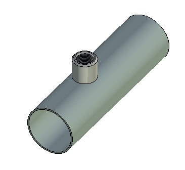
Copy/Paste» for 3D Objects
Command "Paste" from clipboard for 3D objects - fragments, operations, construction elements – was substantially enhanced. Section "Objects" in dialog displays list of objects copied to the clipboard. You can select active object for further transformations. Object insertion is similar to insertion of 3D fragments, with the ability to specify source and target coordinate systems. Special window contains the list of transformations that can be used to control, create and delete transformations and set exact values. Now you can also create target coordinate system based on geometric fixings.
|
|
Sheet Metal
Major improvements were done in the sheet metal commands. Algorithms for operations were improved. Now operations "Bend”, “Unbend”, “Re-bend" can work with ruled faces on the side. If the side face is curved, then the operation will still be feasible, however, the side face geometry thus becomes ruled.
New operation "Convert Solid to Sheet Metal" was introduced. This operation is used to create sheet metal parts from geometry of solid body. The command lets you specify the thickness, bends, and rips necessary to convert a solid part to a sheet metal part. When using the “Convert Solid to Sheet Metal” command you can keep the solid body for other modeling operations.
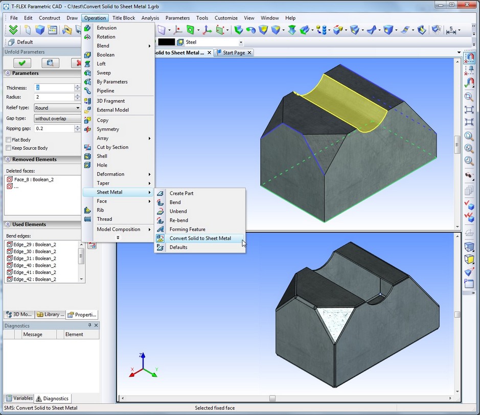
Sheet metal commands now have option to turn on/off check for self-intersection of result.
Changes in 2D Drafting Commands
Image Lines
New mode of image line creation was introduced – image line created with one click between two intersection points. This mode allows you to create image line along construction between its intersections with two other constriction lines. At the same time several clicks in a sequence of such neighboring segments will created just one united image line if image line parameters are the same. The same united result may be obtained by pressing left mouse button, dragging and dropping on the end. Double click on construction, except straight endless lines, creates image line image along complete construction, for example, full circle.
2D Nodes
Command for editing nodes got options for snapping - intersection of construction lines, center of circle, intersection of two snap options (e.g., two perpendiculars), etc.
Command for editing nodes now supports dynamic modification mode. When enabled, node displacement automatically leads to update of related elements. In this case dynamic preview will correspond to the final result.
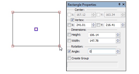
Sketch
Sketch command now has the possibility of constructing a rectangle by center and point in both normal and parametric modes.
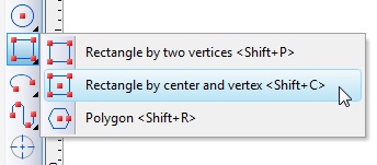
Creation starts with center point definition. Then you define rectangle by corner point. You can also enter exact values of height and width in the properties dialog.
User-defined Lines
Functionality of user-defined image lines was improved. Line thickness now considers settings from document (Status). Outward extensions correspond to line thickness.
Leader Notes
Now after the last point of the leader note is entered, focus automatically goes to the text editor.
If you enter text in the editor and press <Enter>, leader note creation will be completed.
Hatch
New more accurate algorithm for computing hatch area, perimeter and center of mass was implemented. The previous algorithm is used only when contour has self-intersections.
Preview mode was added in "Draw Hatch" command.
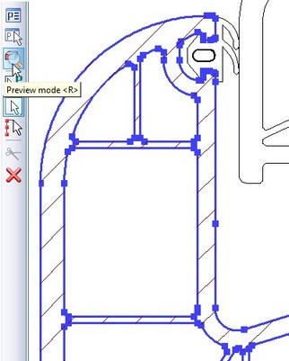
When turned on this mode will immediately display hatch being created with parameters that are specified in the command in case of closed contours.
You can enable/disable this mode by appropriate button or key <R> in automenu.
2D Text
Update of the table contents was improved. Now table associated with the database is always updated on model/drawing recalculation.
Databases
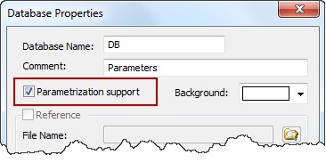
Internal Databases with Parameterization
New possibility was added to databases – usage of variables and expressions inside the databases. This possibility can be enabled with the new flag in properties - «Parameterization support». This parameter can be set on database creation.
When this flag is on, values in the database cells can be assigned to variables and expressions. They will update in accordance with the values of appropriate variables on model recalculation.
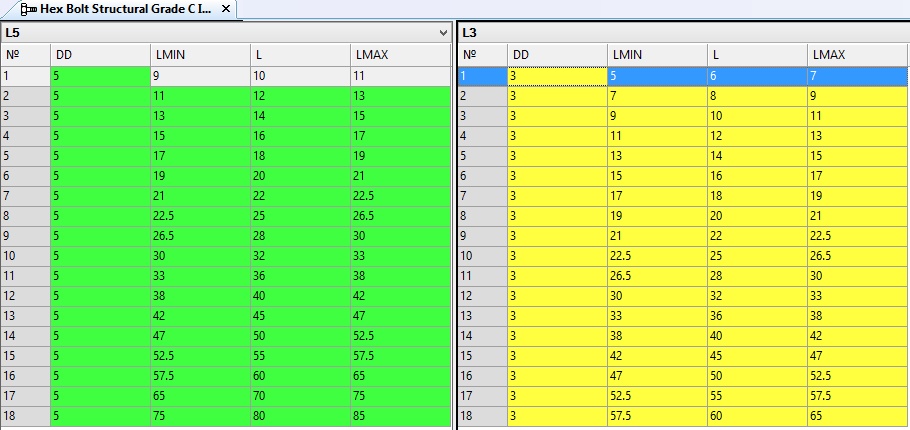
Database Background Color
Background color of database editor can be changed. This feature helps to operate with multiple tables.
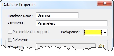
Background color may be different for different database.
New Functions for Getting Values from Database
New functions for operating with databases were added in variables editor:
●db_sum() – sum of values in cells within the range;
●db_mid() – average value in the range;
●db_max() – maximum value in the range;
●db_min() – minimum value in the range.
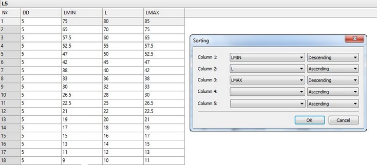
Sorting Database by Several Columns
New «Sorting» command allows to sort database by several columns simultaneously.
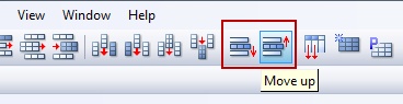
Controlling Order of Records from Toolbar
Commands «Move down» and «Move up», earlier available only from keybaord (Ctrl+Down and Ctrl+Up) now can be used from database toolbar.
Printing Database Contents
Database table contents can be now printed.
Variables
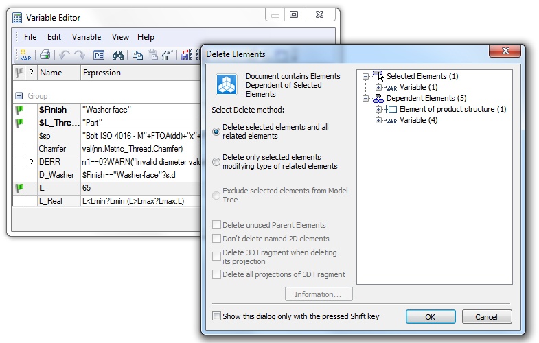
Command «Delete» in Variables Editor
"Delete" command in the variable editor is now available even for variables that are used. If variable is used, user is prompted to either remove the chain of dependent elements or replace the selected variable for a constant value.
Controlling Order of Variables from Toolbar
Commands «Move down» and «Move up», earlier available only from keybaord (Ctrl+Down and Ctrl+Up) now can be used from variables editor toolbar and text menu.
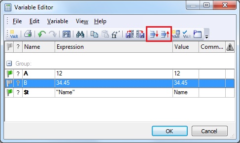
In case one of the columns is enabled for sorting, functionality for order changing will be unavailable.
New Parameters of Functions getv() и tgetv()
New parameters for function getv():
●«DPAGE» - current number of the drawing (normal) page.
●«DPAGES» - number of the drawing (normal) pages.
New parameters for function tgetv()
●tgetv("_FORMAT") – get text string of paper size format from the page where fragment is inserted.
●tgetv("_SCALE") – get text string of scale from the page where fragment is inserted.
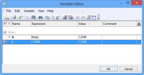
Function for Converting Numeric Value to Text
New function ftot() converts numeric variable to text string using comma instead of dot.
User Interface Enhancements
Large Icons in Automenu
Automenu now uses large icons in case «Large Icons» mode is set for the whole system.
Managing Views
New command «Views Placement» («Window|Views Placement») allows you to split current window into various views or change the type of view.
When calling the command there are several options for each view and their location.
Buttons at the top of the dialog allow you to specify with a click one of the preset configurations of views placement in the working window.
Option "Set as default" allows user to set the selected option of views placement automatically when you create a new document during the current session. Dialog for view placement options will not appear in this case.
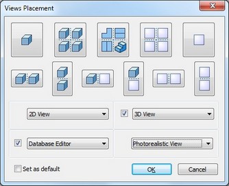
The dialog lets you divide the working space into two or four views and also set the type of each view.
The setup for the views is stored within the document file. Besides 2D and 3D views there are two new types - «Database Editor» and «Photorealistic View».
Full-screen Mode Control via Keyboard
New way of switching to full screen mode was added. It may be toggled using <F11> key.
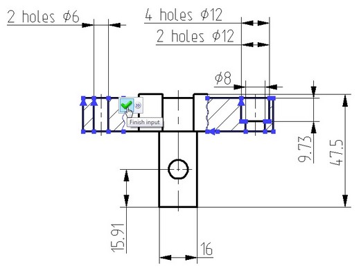
Confirmation Toolbar
Interface of some commands now uses dynamic toolbar with the confirmation button, which appears near the point of the cursor location when the command has enough data to confirm user's actions.
In this case, user is able to quickly confirm his actions using only mouse without having to move the cursor to automenu or properties dialog.
For 2D drafting this option is available in hatch creation command (when closing the contour), when creating 2D paths, 2D splines, pictures, fragments, chains of dimensions, leader notes, GD&T and roughness symbols, when creating copies and arrays.
Dynamic toolbar is also used in some 3D commands, e.g. «Extrusion» and «Blend» after releasing manipulator.
If you want to abandon the use of this feature in the command, you can disable it using option "Do not use in the current command”.
Dynamic Toolbar Display
Dynamic toolbar that appears above the cursor is now displayed by default in transparent mode.
Transparency level changes when cursor gets closer to the toolbar.
You can turn off transparency using the context menu for this toolbar.
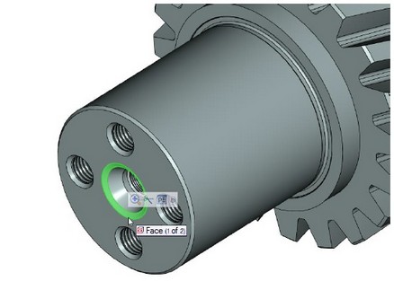
User-defined Commands for Inserting Fragments
"User Commands" dialog has new option for creating new type of commands for inserting fragments.
When you create such command, you can specify the path to the fragment that will be inserted into the current document by clicking on this button.
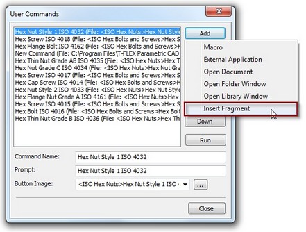
Image of icon for the command can be taken from the fragment file itself.
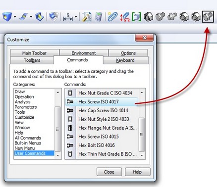
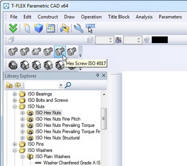
Button Creation Based on Libraries
In «Library Explorer» window the new command was added - «Create Toolbar».
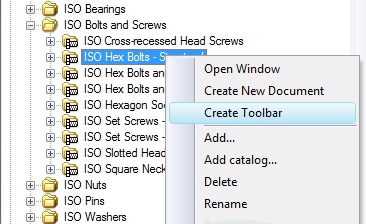
When it is executed, interface of the program will have a new toolbar that contains buttons with commands for inserting elements of the corresponding library. This feature allows you to quickly create toolbar for fast operations with standard and custom libraries.
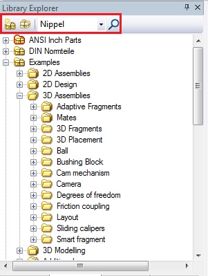
Toolbar in “Library Explorer”
New toolbar was added to «Library Explorer». It helps you to search document in library by its name or portion of name as well as open existing library configuration or create a new one.
Support for Multi-touch Sensor Screens
If you install program on a touch-enabled computer, you can use flick touch and multi-touch gestures. Combination of touches and gestures with one, two, three and four fingers provide most of the functions for rotation, moving, zooming, selecting items, calling the context menu, setting the standard camera positions. Touch recognition allows full usage of systems based on modern Windows versions and touch-enabled devices like tablets and monitors.
Managing Layers
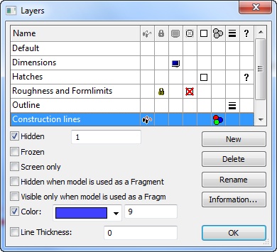
Dialog for «Layers» command was enhanced. It supports now the following new features:
●Size of the dialog can be changed. This simplifies operations with large number of layers.
●Icons responsible for the layer settings are displayed in separate columns. You can sort list of layers by any of the columns.
●Layer parameter can be changed by simply clicking setting icons.
●It is possible now to delete not only unused layers but also layer which is used in some elements. In case of deleting layers used in elements there are two variants of user behavior – delete the layer together with all elements placed on this layer, or transfer these elements to another layer.
●Button "Information ..." allows you to see list of elements placed on the selected layer.
●Setting parameters can be done for multiple selected layers simultaneously.
●Turning on/off the layer parameters is synchronously displayed in the document window. Each action of layer modification is independently registered in the list of actions for possible Undo action.
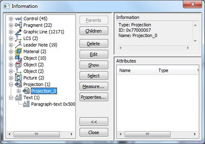
Layers are now displayed in "Information” dialog for all system objects in the list of parent objects.
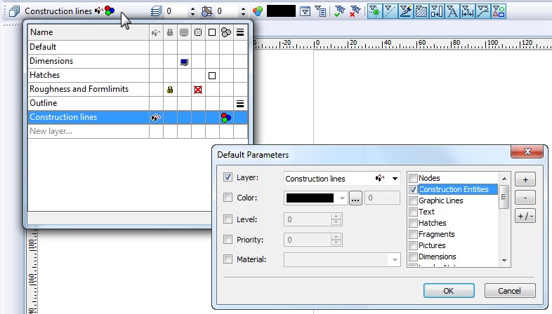
Dialog control for layer selection in the system toolbar was improved. Its drop-down part is now resizable. The list can be sorted by various layer parameters. Clicking an icon will change layer parameter in transparent mode without leaving the current command. The list has line "New layer ...", which allows to create a new layer and make it active.
Import/Export of 3D Graphics
Support for the following 3D graphics formats was added or improved:
Format |
Export |
Import |
Import with textures |
TF3D |
+ |
+ |
+ |
PDF 3D |
+ |
|
|
U3D |
+ |
|
|
X3D |
+ |
+ |
+ |
OBJ |
+ |
+ |
+ |
PLY |
+ |
+ |
|
3DS |
|
+ |
+ |
STL |
+ |
+ |
|
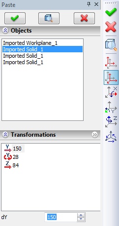
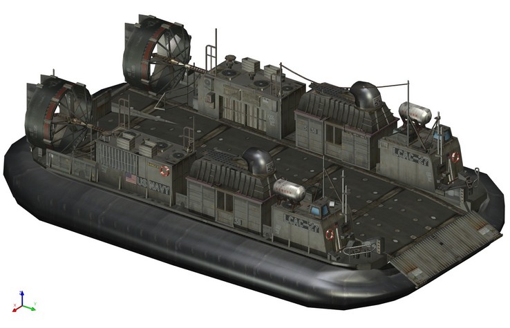
Program now supports many more formats of files that present models as 3D mesh. They can be either exported for usage in other systems or inserted as 3D pictures. Depending on the format various data is supported besides geometric polygons, including color, textures, transparency. TF3D format is a proprietary format recommended for further usage in documents. Other formats present the post popular formats used in 3D graphics.
«3D Picture» command now in addition to VRML and IV formats provides support for insertion the following types of files: X3D, 3DS, OBJ, PLY, TF3D, STL.
X3D |
|
3DS |
|
OBJ |
|
PLY |
|
«Print 3D» Command
New «Print 3D» command is intended for saving model to format readable by 3D printers and devices for rapid prototyping. The command will save current model to STL format which is the de facto standard for 3D printing with options to specify accuracy of generation.
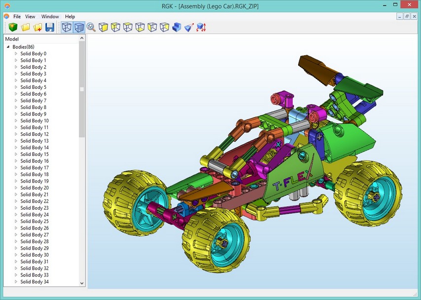
Export to RGK
Support for solid model export to RGK geometric kernel was added in two formats:
●RGK_XML – open xml-based format
●RGK_ZIP – compressed compact format
Data exported to RGK kernel can be viewed by freely distributed viewing applications that may be downloaded from www.rgkernel.com (for Windows) or https://play.google.com/store/apps/details?id=com.rgk.viewer for Android devices. Android-based systems support only RGK_XML.
3D Picture Command
Enhancements were done in 3D Picture command.
●Command provides dynamic view of the edited object in accordance with its parameters and transformation.
●Graphic manipulator is used for applying transformations analogous to 3D fragments.
●3D pictures insertion can be performed using drag and drop from Windows Explorer or any other source directly into the 3D window.
In addition, material can applied now to 3D pictures. If material is not specified, it is taken from the 3D picture itself if exists.
Material to 3D picture can be applied either directly in the properties dialog or by dragging from the materials window.
Other Changes
New Format for Documents
File format for storing documents was reorganized. It is more efficient and reliable especially for large documents. Also it is more compact and saves disk space.
New Parasolid Release
New release of Parasolid kernel is used for internal system operations - 26.1. This kernel has improved handling of complex cases in all kinds of blend, loft, and sweep operations, in surface modeling and Booleans, tapering, shelling and other 3D modeling operations. There are new various options in the modeling commands.
T-FLEX Open API
New classes of Open API were developed including support for creation/editing of the pipeline path. Various tools were added to support transformation of objects.
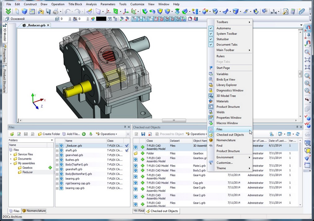
Opening T-FLEX DOCs Windows
Now it is possible to open T-FLEX CAD in windows of T-FLEX DOCs datasets. Windows restore their position on T-FLEX CAD restart.
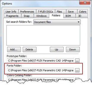
Folder for Searching Fonts
«Options» command now allows to specify folder for searching SHX font files. This folder may be used instead of default folder for such fonts.
Using Comma when Setting Numeric Values
It is no possible to have commas instead of dots when using numeric variables inserted in text. This option can be set in «Status» command on the «Screen» tab.
Selection of Color from Color Catalogs
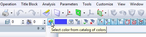
In all dialogs of parameters and other control elements it is now possible to choose color from catalogs of colors. Extra button "..." is added next to the drop-down list of standard colors. Click on the button will open color selection dialog.
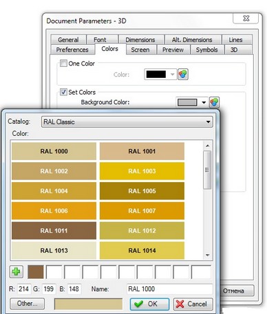

Catalog of colors contains set of pages (left list) containing colors. Each color is defined as RGB components and name.
Besides the list of catalog colors, the dialog contains 10 favorite colors, which user can create from the list and have direct fast access to them.
Each catalog of colors is stored in a separate file with .acb extension. To modify the catalog of colors you can use any text editor or one of the editors available for editing .acb files. By default, system catalogs of colors are located in system folder “Program/ColorBooks”. You can change this path in "Options" command at the "Folders" tab.
To open catalogs of colors from the system toolbar use the corresponding button left to the color list.
«Information» Dialog
Dialog "Information" was enhanced. Now the dialog works in non-modal mode. This means that the user has access to all tools of navigation inside and between windows and pages of the current document. You can use zoom/pan commands and perform other activities that do not change the composition of the current document. Dialog closes automatically when you move to window of any other document, when the document is closed, as well when you remove objects in the current document, change their properties or create new objects.
When you open dialog "Information" and there is large number of document objects (> 1000), objects in the dialog are grouped by folders corresponding to object types.
Printing
Option for selecting uneven pages was added to the dialog box of printing parameters.
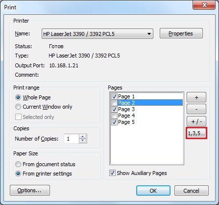
In combination with the reverse selection, it allows you to quickly make a choice of the uneven or even pages to print multi-page documents.
Page size may be set either from document page parameters (Status) or from printer settings.
T-FLEX Analysis
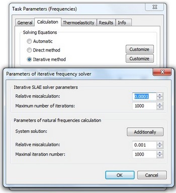
Iterative Frequency Solver
New iterative method of calculations is supported now for solving equations for frequency analysis studies. The new solver allows to increase dimension of the study, compared to the algorithm used previously.
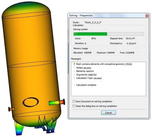
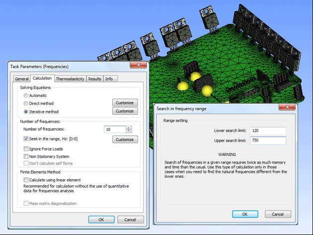
Search of Natural Frequencies in Range
Now you can specify range (lower and upper frequency) to find the given number of natural frequencies of models that fall into this range.
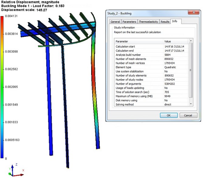
Iterative Buckling Solver
New iterative method of calculations is supported now for solving equations for buckling analysis. The new solver allows to increase dimension of the study, compared to the algorithm used previously.
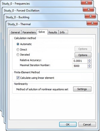
Automatic Selection of Solving Method
Automatic selection of method for solving equations (direct or iterative) is added for the following studies:
●Frequency analysis;
●Buckling;
●Forces Oscillation;
●Thermal Analysis.
Memory Optimization for Multiple Results
In some studies (e.g., transient heat transfer, forced oscillation, calculations with geometric nonlinearity) calculating process generate data at each force or frequency step. Previously, all of the data was stored in RAM during the entire calculation process. Now data is paged out on creation and loaded into memory as needed to use. This makes it possible to perform the calculation with large number of time and force steps, limited only by the size of disk space.
Optimization for Opening Large Results
Speed of opening large results was increased several times ensuring comfortable work with the results, even with millions degrees of freedom.
Nonlinear Statics for Laminar Elements
For studies based on laminar finite elements it is possible now to consider the change in construction stiffness during deformation (geometric nonlinearity). In previous versions this mode was available only for the studies based on tetrahedral finite elements.

Thermal Studies for Laminar Elements
Module allows the steady and unsteady heat calculations for thin (shell) structures modeled by laminar triangular finite elements (shells). For calculation it is possible to use finite elements with linear and quadratic approximation of the thermal fields. Solution of the equations can be achieved by direct or iterative methods. Nonlinear problems of heat radiation into the surrounding space can be also solved.
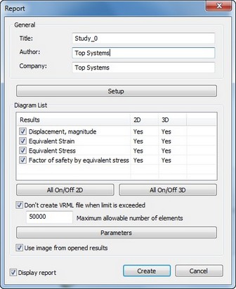
New Dialog for Generating Reports
Dialog of report generator was redesigned. Configuring list of displayed results was simplified. New option can limit the generation of VRML 3D file depending on the dimension of the study. By default, VRML model is not generated when the problem dimension exceeds 50,000 degrees of freedom. User can disable this limitation or set another threshold.
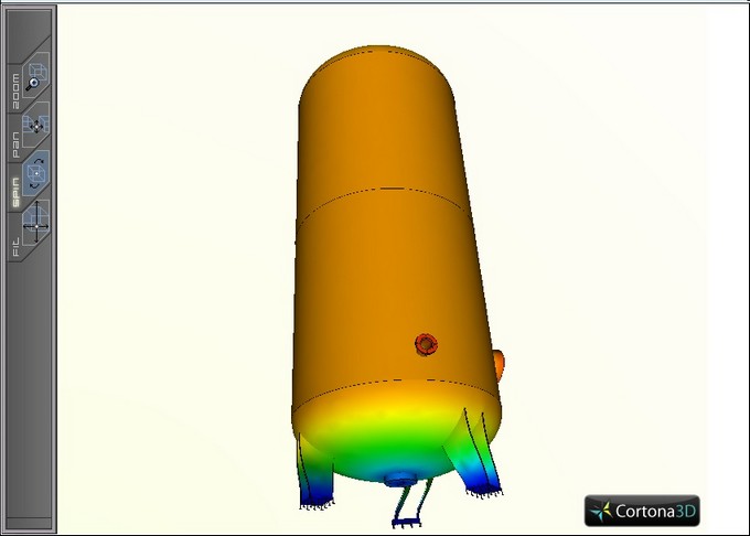
VRML Generation Optimization
VRML model was optimized – size was reduced to simplify its operations in HTML-viewers.
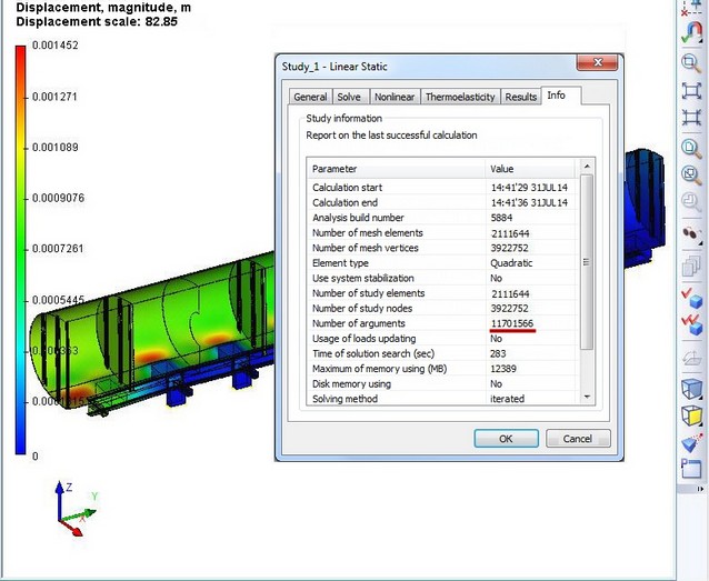
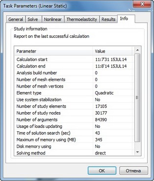
Information Tab
Study properties now have special tab "Info", which outputs general information about successful completion of the calculation.
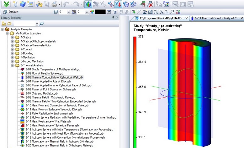
Verification Examples Library Enhancement
Library of verification examples illustrating the accuracy of calculations was supplemented by a large number of new examples with detailed descriptions of the numerical and analytical solutions. The total number of examples now exceeds 90 descriptions.