Printing a Single Document


Printing a Single Document |
|
T-FLEX CAD documents are printed out using the command "File|Print…" ("PT: Print Model"), which is similar to printing commands of most Windows applications. This command allows outputting a single (current) T-FLEX CAD document to a printer or other hardcopy-making device.
However, one may often need to print a whole batch of drawings, arranging those economically on one or several sheets of paper of the specified format. In this case, one can use an additional command "Print documents". This is an external T-FLEX CAD application, which allows composing the required pack of drawings and optimize their placement for printing on sheets of the specified size. The composed batch is created in the current T-FLEX CAD document. The drawings included in the set will be represented in the resulting joint document as internal 2D pictures with the preserved connection with the source files. The resulting document is then printed out just like an ordinary T-FLEX CAD document.
Follow below are the descriptions of both methods for printing T-FLEX CAD documents.
2D drawings can be printed as well as 3D models. It is important, which window was active at the time of calling the print command. Printed are all elements that are visible on the screen, except those on the layer assigned the «Screen only» attribute. Please also keep in mind that construction elements are not printed by default.
To print out a drawing, call the command "PT: Print Model":
Icon |
Ribbon |
|---|---|
|
|
Keyboard |
Textual Menu |
<PT>, <Ctrl><P> |
File > Print |
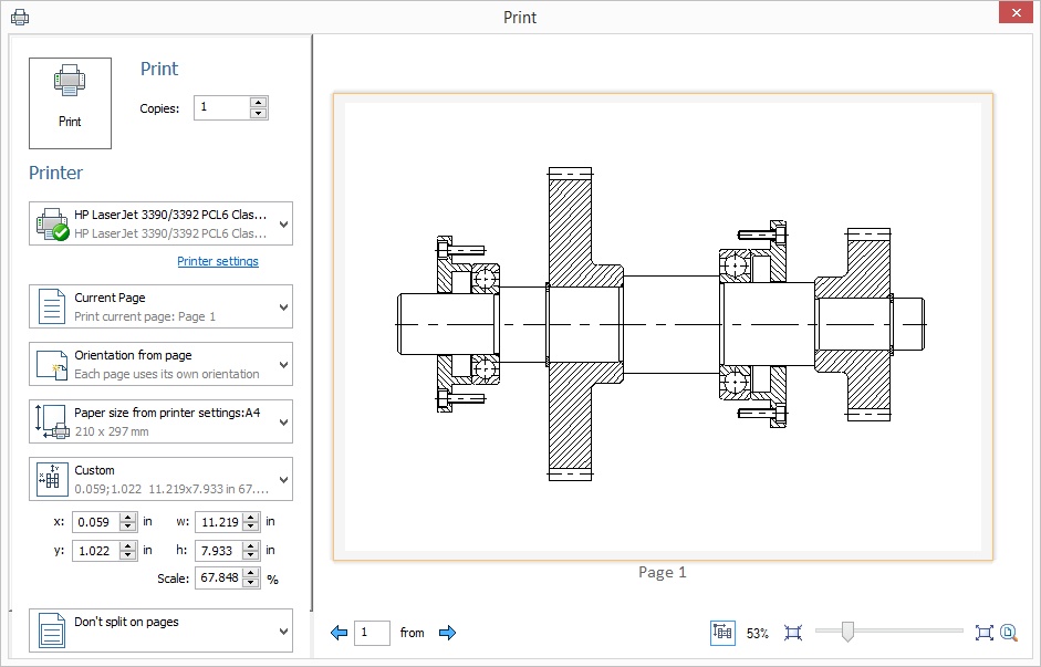
Upon calling the command, the «Print» dialog box appears.
Copies. Sets the number of document copies to print.

Printer. Specifies the printer from the list. The list displays all installed printers.
The button Printer settings calls the Windows dialog for setting up properties of the selected printer; it allows specifying print quality, page parameters etc.
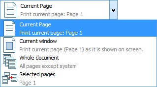
Current Page. Upon setting this parameter, the printout will contain the image displayed in the current window, including portions of the image outside the format frame.
Current window. Upon setting this parameter, the printout will contain only the contents that fit inside the format frame.
Whole document. All document pages of “Normal”, “Text” and “Bill of materials” type will be printed. If a 3D view was active upon calling print command, it will be also printed.
Selected pages. When printing a multi-page drawing, you can specify which pages to print. A list with available pages appears. You need to set the flag near required pages or use one of the options.
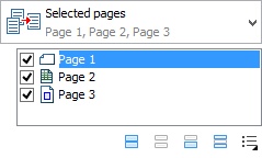
![]() Select all. All pages available in the list will be selected.
Select all. All pages available in the list will be selected.
![]() Deselect all. Cancels pages selection.
Deselect all. Cancels pages selection.
![]() Invert selections. Invert pages selection.
Invert selections. Invert pages selection.
![]() Only print odd pages. Only odd pages will be selected from the list.
Only print odd pages. Only odd pages will be selected from the list.
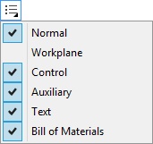
![]() Filter. Allows to select pages types that will be displayed in the list.
Filter. Allows to select pages types that will be displayed in the list.
You can also select 3D view for printing, if it is available in the current window. Upon 3D view printing, dynamic selection of the printed bitmap resolution depending on the printer DPI and scale is performed.
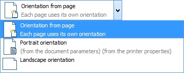
Orientation from page allows to specify each page orientation individually.
Portrait orientation. Sets portrait orientation for all printed pages.
Landscape orientation. Sets landscape orientation for all printed pages.
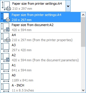
From document. Paper size is controlled by settings of the current document.
From printer’s settings. Size of the paper that will be printed out will be determined by settings of the printer. This mode is enabled by default.
You can also select paper size from the list manually.
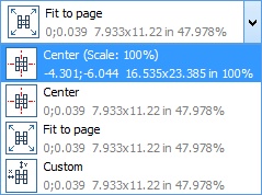
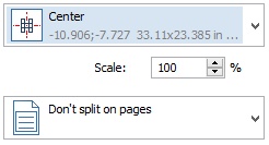
Center (Scale: 100%). Makes the image automatically centered on the sheet at 100%.
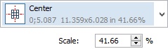
Center. Makes the image automatically centered on the sheet. You can set its scale manually.
Fit to page. Setting this parameter scales the drawing so as to fully fit on one page.
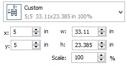
Custom. Allows you to specify image position on the drawing and its scale manually.
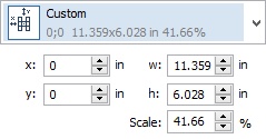
Left and Top. These parameters define the left and top margins of the paper sheet, respectively.
Width and Height. Set the width and height of the printed image.
Scale. Sets the image scale.
If one of the three latter parameters is manually modified, the other two are adjusted automatically to maintain the drawing’s aspect ratio.
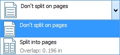
Don’t split into pages. A drawing will be printed on one page.
Split into pages. Use this option when a drawing needs to be printed at a strictly defined scale while the full image does not fit on one page. The option will let you automatically distribute the drawing over multiple pages. The result can be preliminarily evaluated in the preview pane.
Upon selecting the option Custom parameter for image location is activated.
Activate Split lines option to print split lines. The option appears only in Split into pages mode.
You can select skipped pages using option ![]() .
.

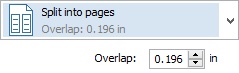
Overlap. This option sets the amount of overlapping between the neighboring sheets when using the Split into pages option. The overlap can be used for gluing separate printed sheets together.
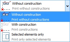
Without constructions. Construction elements will not be printed.
Print Constructions. Setting this parameter makes construction elements printed as well.
Selected elements only. Enabling this flag allows us to print out only selected elements of the drawing.
The parameters managed in Print dialog are retained and displayed upon subsequent opening of the print dialog.
Printing Settings dialog
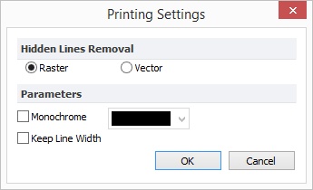
Hidden Line Removal. You can specify the method of removing hidden lines from the drawing: Raster or Vector removal. This option is important when outputting a drawing to pen plotters that require vector hidden lines removal.
Monochrome. This option makes the drawing printed all in one color.
Keep Line Width. Setting this parameter helps avoid variations in line thickness when printing a document at a scale other than 100%.
Preview window is located in the right pane of the dialog.
Its scale can be specified in the right bottom corner.
![]()
To zoom in and zoom out use options ![]() and
and ![]() . Option
. Option ![]() allows to fit page.
allows to fit page.
Options ![]() and
and ![]() allows to select pages in preview window.
allows to select pages in preview window.
Several pages can be shown in preview window when you zoom out. If their display takes a long time, their content is not displayed and ![]() button appears in the bottom of the dialog.
button appears in the bottom of the dialog.
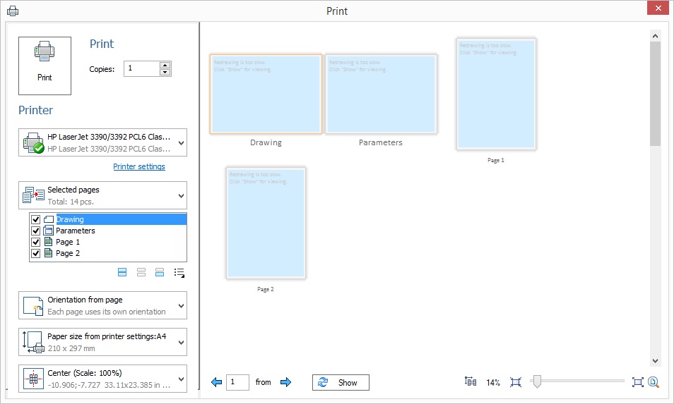
Selected page is highlighted with orange frame.
Option ![]() allows to select position and scale of the printed area manually. You can move printed area with pressed left mouse button. Mouse wheel rotation allows to change scale of the printed area when the option is active. The drop-down list switches to the corresponding location parameter according to the changes.
allows to select position and scale of the printed area manually. You can move printed area with pressed left mouse button. Mouse wheel rotation allows to change scale of the printed area when the option is active. The drop-down list switches to the corresponding location parameter according to the changes.
Printers’ fields are showed with grey in preview window. There are no fields for virtual printer.
After all parameters setting press Print button in the top left corner.
Dialog from the previous versions of T-FLEX CAD is also available.
If you want to use legacy version of printing dialog box, you need to set option Legacy printing on Additional Options tab in Options command.
![]()