Replace Faces


Replace Faces |
|
General concepts
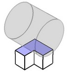
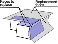
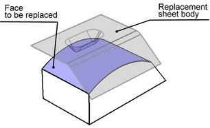
This command allows replacing a geometrical surface underlying the selected face, by another geometrical surface.
In the usual command flow, the faces to be replaced are selected in pairs with the replacement surfaces (by selecting elements with these underlying surfaces). The surface underlying the face being replaced is substituted by the replacement surface. As a result, the face being replaced changes its shape according to the shape of the replacement surface. The side faces that bound the face being replaced are extended or trimmed to the intersection with the replacement surface. If several pairs of faces to replace - replacement surfaces were selected at once, this procedure is repeated for each pair.
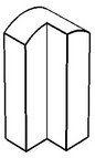
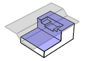
It is possible that no intersection between the side faces and the replacement surfaces will be found despite extending the side faces. Then the command will end up in an error message.
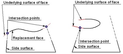
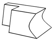
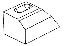
Command is successful Command fails
Using the command
The command "3ZR: Face Replace" can be called as follows:
Icon |
Ribbon |
|---|---|
|
3D Model → Special → Faces → Replace Faces |
Keyboard |
Textual Menu |
<3ZR> |
Operation > Face > Replace Faces |
To create the operation, do the following steps:
1. Select sets (pairs) of faces to replace and the replacements.
2. Define advanced parameters (optional).
3. Confirm operation creation.
Selecting faces to replace and replacements
You can select multiple pairs of faces to replace and replacement surfaces.
To select faces to replace, use the option:
![]() <F> Select replaceable faces
<F> Select replaceable faces
A face to replace could belong to a sheet body, but in that case it should be "surrounded" by adjoining faces on all sides.
To select replacement faces, use the option:
![]() <R> Select replacement faces
<R> Select replacement faces
When specifying replacement faces, you can select not only faces, but also edges, workplanes and 3D profiles. Selecting a workplane or a flat 3D profile is similar to selecting an appropriately positioned flat face. If a non-flat 3D profile was selected, the system will use its underlying surface as the replacement. An edge can be selected if it fully lies in a plane, but is not straight.
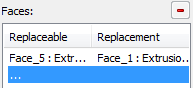
You can also start selecting a face to replace and a replacement surface via the property window. Working with the "Faces" list is similar to working with other such lists.
Besides simply selecting the replacement surfaces, it is also possible to select a sheet body. The following option is used for this purpose:
![]() <S> Select sheet body
<S> Select sheet body
When using this option, you can select sheet bodies, faces and 3D profiles.
The faces being replaced will be replaced by one or multiple new faces copying the shape of the replacement sheet body.
While only a single sheet body is allowed, you can select multiple faces to replace at once.
When using a sheet body, the faces to be replaced may not have holes, otherwise the command will fail. Besides that, the replacement sheet must be large enough, so that the intersection could be constructed between the replacement sheet and the extensions of the adjacency faces.
To cancel selection of a particular pair of the face to be replaced - the replacement surface, you can use the properties window and the button ![]() . As for canceling selection of all faces, you can use the option:
. As for canceling selection of all faces, you can use the option:
![]() <X> Cancel selection of all faces and surfaces
<X> Cancel selection of all faces and surfaces
Selection of the replacement sheet body can be canceled by the option:
![]() <K> Cancel sheet body selection
<K> Cancel sheet body selection
Defining advanced parameters
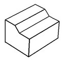
As was mentioned above, the adjoining faces are grown or trimmed to the intersection with the replacement surfaces. If two intersections are found, which one will be picked by the system? By default, the intersection is accepted with the part of the surface where the normal points towards the faces to be replaced.
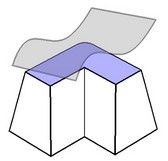
However, in some cases, you may want the system to pick the second intersection choice. For this purpose, use the "Reverse" flag, located at the lower portion of the property window.
![]()
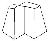
If the flag is set, the system will pick the intersection with the portion of the replacement surface, whose normal points away from the face being replaced.
|
"Reverse" is Off |
"Reverse" is On |