Roughness Symbols


Roughness Symbols |
|
Roughness notation symbols creation is similar in its nature to creating leader notes and tolerances. First, you define the position and attachment of the roughness, and then specify its parameters. The size of a roughness element is related to the font size defined either in the parameters of the specific element, or in the command "ST: Set Document Parameters", the tab "Font".
Creating Roughness Notation
To apply a roughness notation, you need to enter the command "RO: Create Roughness Symbol":
Icon |
Ribbon |
|---|---|
|
Draw → Title Block → Roughness Symbol |
Keyboard |
Textual Menu |
<RO> |
Draw > Roughness Symbol |
The following options will become available to you in the command:
|
<Enter> |
Place a roughness symbol at the pointer position. |
|
<Alt+P> |
Copy Properties from Existing Element |
|
<P> |
Set Roughness Symbol Parameters |
|
<N> |
Set relation with Node |
|
<L> |
Set relation with Line |
|
<C> |
Set relation with Circle |
|
<D> |
Set relation with Dimension |
|
<R> |
Set Relation with Leader Note |
|
<E> |
Set relation with Ellipse |
|
<S> |
Set relation with Spline |
|
<T> |
Link to Node |
|
<Space> |
Change Roughness Attach type |
|
<Z> |
Change leader line jog orientation (available only with selection of the previous option) |
|
<K> |
Break (kill) relations (available upon selecting attachment element) |
|
<F4> |
Execute Edit Roughness Symbol command |
|
<Esc> |
Exit command |
The roughness can be instantly placed in the absolute coordinates at the pointer position by clicking ![]() . An exact value of coordinates can be defined in the command's properties window (the section “Coordinates”).
. An exact value of coordinates can be defined in the command's properties window (the section “Coordinates”).
The way of attaching the created roughness is determined by the status of the option ![]() . This option contains a drop down list with the following choices:
. This option contains a drop down list with the following choices:
![]() <Alt+N> Roughness without leader jog
<Alt+N> Roughness without leader jog
![]() <Alt+L> Roughness with leader jog
<Alt+L> Roughness with leader jog
![]() <Alt+T> Attach to the sign point
<Alt+T> Attach to the sign point
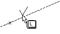
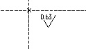
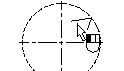
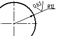
To attach a roughness symbol to a construction or graphic line (ellipse, spline, path or function), use the respective option <L> (<E>, <S>). The graphic pointer must be over the desired line when using the option. The intended construction entity must have at least one node on it. In this way, the roughness being created is attached to the entity and the nearest node on this construction entity. A leader line will be created by default from the node to the roughness symbol (you can cancel the leader line creation in the command's properties window).
With the object snapping engaged, to select an attachment element you just need to move the pointer over the desired element. As the element pre-highlights and the pointer changes its shape, indicating snapping to the element, click ![]() . In complicated configurations, you can use the element selection options for precise element selection.
. In complicated configurations, you can use the element selection options for precise element selection.
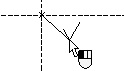
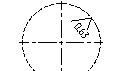
Upon selecting the construction or graphic entity (ellipse, spline, path or function), a roughness symbol starts rubberbanding with the pointer. To complete the creation, point the mouse to the desired position of the roughness symbol (the distance from the node to which the roughness being created is attached) and click ![]() .
.
A precise position of the roughness on a construction or graphic line can be defined in the command's properties window.
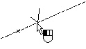
For attaching to a node, select the desired node by pressing the key <N>.
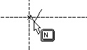
When selecting a node, the roughness can be created in two modes: with an offset from the node and without an offset. By default, the mode of snapping to the node without an offset is used. This is indicated by the enabled option ![]() in the command automenu. In this case, you just need to point at a node and click
in the command automenu. In this case, you just need to point at a node and click ![]() . To set the mode of snapping to a node with an offset, disable the option
. To set the mode of snapping to a node with an offset, disable the option ![]() . In this case, after selecting the snap node you will need to specify an offset relative to the node for the roughness. This can be done by
. In this case, after selecting the snap node you will need to specify an offset relative to the node for the roughness. This can be done by ![]() in the drawing window or by entering the exact offset value in the command's properties window.
in the drawing window or by entering the exact offset value in the command's properties window.
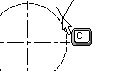
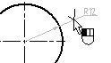
A roughness symbol can be attached to a circle (the option <C>).
The dimension is selected by the key <D>.
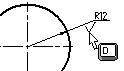
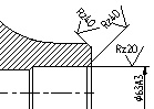
A roughness can also be attached to graphic lines. As the pointer approaches a graphic line, the entity is pre-highlighted due to the object snapping. If the roughness symbol is placed beyond the graphic line limits, then by default a leader is created along the graphic line extension up to the roughness symbol (the leader creation can be disabled in the roughness parameters).
To undo element selection (line, node, circle or dimension), and, thus, to cancel the attachment relation, use the option ![]() .
.
To cancel the last action (for example, to cancel the leader start attachment), use the <Esc> key or right click ![]() .
.
Roughness parameters are defined in the command's properties window prior to specifying the roughness position on the drawing. Besides that, you can enter the exact position of the roughness snap point in the properties window. Option ![]() will take parameters of roughness symbol from already existing roughness element. See chapter "Dimensions" for more details on this option.
will take parameters of roughness symbol from already existing roughness element. See chapter "Dimensions" for more details on this option.
Roughness Parameters
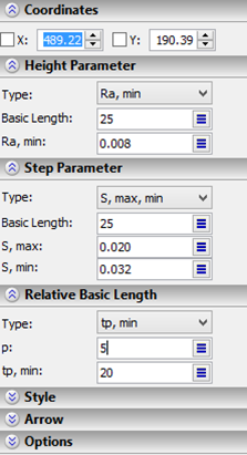
The first section – “Coordinates” – provides the fields to enter the exact coordinates of the roughness snap point. The current coordinates are dynamically tracked as the cursor moves in the drawing window.
The other sections of the properties window – “Height Parameter”, “Step Parameter”, “Relative Basic Length” – may contain various sets of parameters, depending on the “Type” field value selections in each section:
Height Parameter. The possible parameter combinations are – “Basic Length” and:
Ra, Ra, max, min Ra, min Ra, nom
Rz, Rz, max, min Rz, min Rz, nom
Rmax, Rmax, max, min Rmax, min Rmax, nom
Step Parameter. The possible parameter combinations are – “Basic Length” and:
S, S, max, min S, min S, nom
Sm, Sm, max, min Sm, min Sm, nom
Relative Basic Length. The possible parameter combinations are:
tp, tp, max, min tp, min tp, nom
Note that the set of values that you can select can be either in the metric or in the inch notation. This is controlled by the parameter “Units” in the command “ST: Set Document Parameters”. Remember that you can use variables (surrounded in braces) in any parameter field.
Besides, each parameter combo box provides the pre-defined list of values. The user can customize this list, modifying and appending it as desired. To edit the list, right click ![]() over the dialog combo box, and select the command “Edit Value List” in the context menu. For detailed information, refer to the chapter “Main Concepts of System Operation”, the topic “Context menu for dialog input boxes”.
over the dialog combo box, and select the command “Edit Value List” in the context menu. For detailed information, refer to the chapter “Main Concepts of System Operation”, the topic “Context menu for dialog input boxes”.
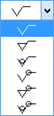
In the “Style” section there are the following roughness parameters:
Symbol. The type of the roughness symbol notation can be selected from the set (see the diagram on the right).
Direction. Is defined by a symbol of icon or special font, invoked by the key combination <Alt><F9>.
Before Symbol, After Symbol. These parameters allow defining additional strings of text to be displayed before and after the roughness symbol, respectively.
Instruction. This parameter defines the string that will be put above the jog.
Unset Roughness Symbol. Creates the notation of unset roughness ![]() . To define the symbol inside the parentheses, set the flag “Symbol in parentheses”.
. To define the symbol inside the parentheses, set the flag “Symbol in parentheses”.
Leader Line. This parameter sets the mode of creating the leader line when attaching the roughness to a line or a graphic entity.
Old Drawing Style. This flag is reserved for switching between old and new roughness notation standards when applicable.
In the “Arrow” section you can define the type and size of the leader arrow. The parameters represented by textual strings allow use of variables (the variables must be surrounded in braces).
The section “Option” contains only one auxiliary parameter– “Show Dialog for each Created Element”. If this parameter is enabled, then the roughness parameters dialog will automatically appear after defining the roughness position in the roughness creation command (the option ![]() ).
).
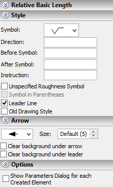
This mode allows working in the same way as in previous versions of T-FLEX CAD – by specifying the roughness position in the drawing first, and then defining its parameters.
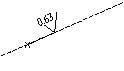
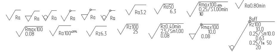
Various samples of the roughness notation symbol are shown below:
Roughness Parameters Dialog
You can also define roughness parameters using the parameters dialog accessible by the automenu option:
![]() <P> Set Roughness Symbol Parameters
<P> Set Roughness Symbol Parameters
The parameters available on the tabs of that dialog duplicate the parameters in the properties window. Besides that, the parameters dialog contains several additional parameters. First of all, those are the system-wide parameters: level, layer, priority, color. There is also an additional tab in the dialog that contains font parameters. There you can define the required font parameters to display the roughness text.
Defining Default Parameters
The default parameters that will be applied to all newly created roughness symbols can be defined in various ways.
First of all, those can be defined using the parameters dialog (the option ![]() ). To do that, call this dialog before creating a roughness. The parameters defined in it will be copied over to the parameters of each newly created roughness symbol.
). To do that, call this dialog before creating a roughness. The parameters defined in it will be copied over to the parameters of each newly created roughness symbol.
Besides that, you can save parameters defined for any roughness being created (or edited) as the default, by clicking the button ![]() in the command's properties window.
in the command's properties window.
Editing Roughness Symbol
The command "ERO: Edit Roughness Symbol" allows changing the attachment, position and the parameter values of a roughness symbol (alternatively, use the option <F4> in the command "RO: Create Roughness Symbol"):
Keyboard |
Textual Menu |
Icon |
<ER> |
"Edit|Draw|Roughness Symbol" |
|
Upon calling the command, the following icons are available in the automenu:
![]() <*> Select All Elements
<*> Select All Elements
![]() <Esc> Exit command
<Esc> Exit command
A roughness symbol notation can be selected by pointing at with the mouse and clicking ![]() , or by multiple selections. As in the case of other drawing elements, multiple selections are done by the option
, or by multiple selections. As in the case of other drawing elements, multiple selections are done by the option ![]() . Using
. Using ![]() together with the depressed key <Shift> adds an element to the list of selected, while with the key <Ctrl> - excludes from the selected list.
together with the depressed key <Shift> adds an element to the list of selected, while with the key <Ctrl> - excludes from the selected list.
For multiple selections, you can use the options:
![]() <P> Set Roughness Symbol Parameters
<P> Set Roughness Symbol Parameters
![]() <Alt+P> Copy Properties from Existing Element
<Alt+P> Copy Properties from Existing Element
![]() <Del> Delete selected Element(s)
<Del> Delete selected Element(s)
![]() <Esc> Cancel selection
<Esc> Cancel selection
When selecting a single element, the properties window displays parameters of the selected element. The following icons become available in the automenu:
![]() <P> Set Roughness Symbol Parameters
<P> Set Roughness Symbol Parameters
![]() <Alt+P> Copy Properties from Existing Element
<Alt+P> Copy Properties from Existing Element
![]() <K> Break (kill) relations (available when the selected roughness is attached to a node, construction or graphic entity)
<K> Break (kill) relations (available when the selected roughness is attached to a node, construction or graphic entity)
![]() <H> Change leader / roughness position (available when selecting a roughness symbol with a leader)
<H> Change leader / roughness position (available when selecting a roughness symbol with a leader)
![]() <Z> Change leader line jog orientation (available only when selecting a roughness symbol with a leader)
<Z> Change leader line jog orientation (available only when selecting a roughness symbol with a leader)
![]() <T> Link to Node
<T> Link to Node
![]() <Space> Change Roughness Attach type
<Space> Change Roughness Attach type
![]() <N> Set relation with Node*
<N> Set relation with Node*
![]() <L> Set relation with Line*
<L> Set relation with Line*
![]() <C> Set relation with Circle*
<C> Set relation with Circle*
![]() <D> Set relation with Dimension
<D> Set relation with Dimension
![]() <E> Set relation with Ellipse*
<E> Set relation with Ellipse*
![]() <S> Set relation with Spline*
<S> Set relation with Spline*
![]() <I> Select Other Element
<I> Select Other Element
![]() <Del> Delete selected Element(s)
<Del> Delete selected Element(s)
![]() <Esc> Cancel selection
<Esc> Cancel selection
* The respective attachment element selection option is available if the selected roughness symbol was defined in the absolute coordinates, or if the attachment of this element was canceled by the option ![]() .
.
Once selected, the roughness symbol starts rubberbanding on the screen, following the pointer. The option ![]() allows selecting which point of the roughness notation to rubberband - the arrow tip or the leader jog. Clicking
allows selecting which point of the roughness notation to rubberband - the arrow tip or the leader jog. Clicking ![]() fixes the roughness symbol in the new position.
fixes the roughness symbol in the new position.
To change the attachment type, first you need to cancel the original attachment by using the option ![]() (<K>). After that, the options will be provided in the automenu for selecting new attachment elements: <N>, <L>, <C>, <S>, <D>. If the position of the selected roughness symbol was defined in the absolute coordinates, then you do not need to use the first option <K>.
(<K>). After that, the options will be provided in the automenu for selecting new attachment elements: <N>, <L>, <C>, <S>, <D>. If the position of the selected roughness symbol was defined in the absolute coordinates, then you do not need to use the first option <K>.
Node, that roughnesses on lines, dimensions and circles can assume two opposite positions.
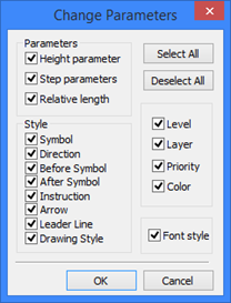
The option <P> allows modifying parameters of the several selected roughness symbols. Modifying parameters in the case of selecting a single element is similar to defining the roughness parameters. However, if you selected multiple roughnesses for editing and run Edit command, then you need to determine first, which parameters to modify, in the "Change parameters" dialog box. By default, all parameters of the selected elements are subject to editing. Upon selecting parameters for editing and pressing [OK], you will access the standard dialog box for defining roughness parameters. Option ![]() takes parameters of roughness symbol from existing roughness symbol. To delete a roughness symbol, select it, and then press the <Del> key.
takes parameters of roughness symbol from existing roughness symbol. To delete a roughness symbol, select it, and then press the <Del> key.