GD&T Symbols


GD&T Symbols |
|
Creating Geometric Dimensioning and Tolerancing Symbols. Datum Symbols
To apply surface geometric dimensioning and tolerancing symbols (from now on – GD&T symbols) or datum symbols, use the command "FO: GD&T Symbol".
A formlimit or datum symbol can be displayed with or without the leader line and contain any number of extension lines.
The size of the GD&T symbols is dependent on the font size specified among the parameters of a particular element or system-wide in the command "ST: Set Document Parameters", the tab "Font".
Creating Tolerancing and Datum Symbols
Enter the command "FO: GD&T Symbol":
Icon |
Ribbon |
|---|---|
|
Draw → GD&T Formlimits |
Keyboard |
Textual Menu |
<FO> |
Draw > GD&T Formlimits |
You will be provided the following options:
|
<P> |
Set GD&T formlimit parameters |
|
<T> |
Copy properties from existing element |
|
<O> |
Create leader or datum with leader/Create leader or GD&T Formlimit with leader |
|
<M> |
Select linked dimension |
|
<N> |
Select node |
|
<L> |
Set relation with line |
|
<D> |
Set relation with dimension |
|
<U> |
Orthogonal Fixing/Fixing to point/Angle Fixing |
|
<Del> |
Delete arrow |
|
<F4> |
Execute Edit GD&T formlimit command |
|
<Esc> |
Exit command |
The ![]() /
/![]() option allows us to select which type of elements will be created – tolerance or datum. The state of the option changes cyclically when we press on it in the automenu or by means of <O> on the keyboard. By doing so, the cursor view and the dialog of command’s properties window will change.
option allows us to select which type of elements will be created – tolerance or datum. The state of the option changes cyclically when we press on it in the automenu or by means of <O> on the keyboard. By doing so, the cursor view and the dialog of command’s properties window will change.
When we start the “FO: Create tolerance of surface” command for the first time, the datum creation mode is automatically set up. The image of the datum with extension appears on the screen next to the cursor. The dialog in the properties window contains the parameters of the datum. In the automenu of the <O> option the |
|
When switching to the tolerance creation mode, the image of the tolerance with extension line appears next to the cursor. In the command’s properties window, the set of tolerance’s parameters is shown instead of datum’s parameters. The icon of the <O> option changes to It is possible to switch between work modes of the command (creation of tolerance/creation of datum) at any stage of command’s work. |
|
When we subsequently invoke the “FO: Create tolerance of surface” command (inside the same work session with T-FLEX CAD), the system will by default prompt us to create that type of the element (datum/tolerance) which was created the last in the preceding call of the command.
Creating tolerance
Creating tolerance with extension line
Specifying location of tolerance
To create tolerance with extension, the user has to specify location of the tolerance on the drawing, shape of the extension, and also tolerance’s parameters.
In general case the tolerance location is determined by sequential indication of two snapping points– snapping point of the extension’s arrow and snapping point of the tolerance itself. Dynamic image of the tolerance on the screen shows which snapping point the user must specify at the current moment. Location of both points can be specified in absolute coordinates and also via snapping to the elements of the drawing.
|
|
Dynamic view when the first snapping point is specified (snapping point of extension’s arrow) |
Dynamic view when the second snapping point is specified (snapping point of tolerance symbol) |
The first snapping point defines location of the extension’s arrow. Snapping in absolute coordinates is carried out by pressing ![]() . Snapping point is created at the current location of the cursor.
. Snapping point is created at the current location of the cursor.
Location of the second point can be defined relative to the first snapping point of the tolerance (with respect to the arrow) or in absolute coordinates. To select the mode, use the option:
|
<F> |
Tie to Arrow |
When this option is enabled, location of the leader is specified with respect to the arrow of the leader note, when this option is disabled – in absolute coordinates.
To snap the tolerance to drawing’s elements it is possible to use object snapping and the following options of the automenu:
|
<N> |
Select node |
|
<L> |
Set relation with line |
|
<D> |
Set relation with dimension |
Object snapping can be used for snapping the tolerance symbol to such elements as construction line (line), graphic line (segment), 2D node, graphic lines that belong to 2D projections or 2D fragments, to points of confluence of graphic lines that belong to 2D projections or 2D fragments (a 2D node is created when selecting a point). It is also possible to read the value of the dimension for automatic calculation of the tolerance. With the approach of the cursor, the elements accessible for snapping will be highlighted. Both the extension line and the tolerance itself can be snapped to drawing’s elements.
To snap to a 2D node or to a point of object snapping, it is sufficient to indicate the desired node/point and press By default, the snapping of a tolerance is carried out to the node itself, without a shift. |
|
|
To specify a shift, it is necessary after specifying location of all snapping points to return to editing of the desired point. After the point is selected it will start to follow the cursor. While doing so, the node will be highlighted and the rubber-band line will extend from it to the cursor. Pressing |
|
|
To return the snapping point to the selected node, i.e., to cancel the shift, use the option:
|
<F> |
Fix to a node |
When snapping to the construction line or graphic line, it is necessary first to indicate the snapping line itself with the help of ![]() . The tolerance’s image will start moving after the cursor along the selected line. Second click of
. The tolerance’s image will start moving after the cursor along the selected line. Second click of ![]() will fix location of the extension’s arrow or of the tolerance itself (in case of snapping the tolerance itself to the graphic line).
will fix location of the extension’s arrow or of the tolerance itself (in case of snapping the tolerance itself to the graphic line).
When snapping to the graphic line, the tolerance symbol can be situated beyond the graphic line bounds – on its continuation
In case of snapping the tolerance’s arrow to the line, it is possible to control location of the arrow with respect to the snapping line. To do so, the following option of the command’s automenu can be used:
|
<U> |
Orthogonal Fixing/Fixing to point/Angle Fixing |
The ![]() option allows us to keep the extension line of the tolerance perpendicular to the selected snapping line. If the tolerance was created with the use of the
option allows us to keep the extension line of the tolerance perpendicular to the selected snapping line. If the tolerance was created with the use of the ![]() option, then while being translated along the line it will be translated “as a whole” (without change in angles). The
option, then while being translated along the line it will be translated “as a whole” (without change in angles). The ![]() option allows us to retain the angle of the extension line with respect to the selected snapping line.
option allows us to retain the angle of the extension line with respect to the selected snapping line.
By default the “Tie perpendicularly” option is activated automatically. Note that in this case after selection of the snapping line it is sufficient to click ![]() only once to specify location of the arrow and of the tolerance itself. That is, the second click of
only once to specify location of the arrow and of the tolerance itself. That is, the second click of ![]() immediately determines location of two snapping points of the tolerance.
immediately determines location of two snapping points of the tolerance.
To cancel snap to the line or node, use the option (available upon selection of the corresponding snapping point of the tolerance):
|
<K> |
Break (kill) relations |
To snap tolerance to a dimension, it is necessary to specify the desired dimension, with the help of object snapping or with the ![]() option in the automenu. After selection of the dimension with the help of
option in the automenu. After selection of the dimension with the help of ![]() , the tolerance is tied to the dimension line. The tolerance’s image will move after the cursor along the dimension line. Additional click of
, the tolerance is tied to the dimension line. The tolerance’s image will move after the cursor along the dimension line. Additional click of ![]() will fix the image of the tolerance in the desired location. The tolerance’s parameters in this case are calculated automatically on the basis of parameters of the dimension. Figures below show examples of snapping tolerance with extension to the dimension:
will fix the image of the tolerance in the desired location. The tolerance’s parameters in this case are calculated automatically on the basis of parameters of the dimension. Figures below show examples of snapping tolerance with extension to the dimension:
There is also a possibility to link the tolerance’s parameters with the dimension’s value, without fixing location of the tolerance to the dimension itself. In the command’s automenu the following option is available:
|
<M> |
Select linked dimension |
The tolerance tied with the dimension with the help of the ![]() option can be positioned on the drawing in an arbitrary way, however, its parameters retain connection with parameters of the indicated dimension. When changing the dimension’s value, the tolerance’s parameters will change automatically.
option can be positioned on the drawing in an arbitrary way, however, its parameters retain connection with parameters of the indicated dimension. When changing the dimension’s value, the tolerance’s parameters will change automatically.
To break connection between tolerance’s parameters and the dimension’s value, use the option:
|
<Ctrl+M> |
Break link with dimantion |
To cancel the snap of the tolerance location to dimension, the ![]() option is used (available when selecting the corresponding snapping point of the tolerance).
option is used (available when selecting the corresponding snapping point of the tolerance).
Markers for controlling the snap of tolerance’s elements. Creation of extension line with bends.
After initial snapping of the tolerance, location of its snapping points can be modified. Also it is possible to change the shape of the extension line by creating any number of bends on it. To control the snap of tolerance’s points, and also for specifying bends on its extension line, the special markers are used.
At the beginning of tolerance creation, there are only two markers – they designate its major snapping points and are highlighted with blue color. After location of both points has been specified, on the image of tolerance’s arrow one more marker appears, highlighted with green color. This is a point in which it is possible to create a bend. |
|
To correct location of any snapping point, it is sufficient to move the cursor closer to the marker of the desired point (it will be highlighted with orange color) and select it with ![]() . The point will start moving after the cursor. In this way, for example, it is possible to specify the shift when snapping the tolerance’s point to the node.
. The point will start moving after the cursor. In this way, for example, it is possible to specify the shift when snapping the tolerance’s point to the node.
To create a bend, it is required to move the cursor closer to the green marker (it will also be highlighted with orange color) and select it with the help of ![]() . The arrow will split into two sectors, flexure point – arrow bend point – will start moving after the cursor. The second click of
. The arrow will split into two sectors, flexure point – arrow bend point – will start moving after the cursor. The second click of ![]() will fix location of the arrow bend point.
will fix location of the arrow bend point.
After creation of the first bend point, new green markers will appear on the created arrow segments. If necessary, it is possible to create next bend on any of these segments. When arrow creation is finished, it is possible either to start creation of the next arrow or complete tolerance creation with the help of the |
|
The following option controls the snap of each bend point with respect to the preceding point of the arrow:
|
<F> |
Attach to arrow |
When this option is enabled, location of the bend is specified with respect to the previous characteristic point of the arrow, when this option is disabled – in absolute coordinates.
To remove the bend point, it is required to select it and use the following option:
|
<Del> |
Delete point |
Creation of additional extension lines (arrows) for tolerance
After location of the main arrow and the tolerance’s image itself has been specified, additional option appears in the automenu:
|
<Space> |
Add arrow |
When this option is invoked, the image of the new arrow-extension appears next to the cursor.
Location of arrow of the additional extension line can also be specified in absolute coordinates or by using the snap to the lines and nodes of the drawing. With the help of markers it is possible to generate bends on the arrow. In the properties window the user can specify individual parameters of the arrow that are different from the specified parameters of the main arrow of the tolerance.
The end of the additional arrow can be snapped to any characteristic point of the tolerance’s rectangle ![]() . (2D nodes can be created in those points if the option “Create Nodes on GD&T Symbol” is active, as defined in the command “Customize|Options…”, the tab [Snap]). The characteristic point nearest to the pointer is automatically selected when picking the GD&T symbol.
. (2D nodes can be created in those points if the option “Create Nodes on GD&T Symbol” is active, as defined in the command “Customize|Options…”, the tab [Snap]). The characteristic point nearest to the pointer is automatically selected when picking the GD&T symbol.
You can reject creation of the new arrow by using the following option:
|
<Del> |
Delete arrow |
The list of created arrows for the tolerance is displayed in the properties window.
The ![]() and
and ![]() buttons to the right of the arrow list can also be used for creation and deletion of the tolerance’s arrows.
buttons to the right of the arrow list can also be used for creation and deletion of the tolerance’s arrows.
Automatic completion of tolerance creation
By default, after specifying location of two main tolerance’s points (location of the arrow and of the tolerance’s rectangle) the command remains in the mode of editing the created element. This allows us to add to the tolerance the required number of additional arrows, create bends on the arrows, specify and edit parameters at any moment of tolerance creation. After creation of the tolerance is finalized, its creation needs to be completed explicitly with the help of the ![]() option or analogous button in the command’s properties window.
option or analogous button in the command’s properties window.
It is also possible to use another work algorithm. In the command’s properties window, in the “Options” section, there is a flag “Create automatically”. When this flag is enabled, the tolerance creation will automatically be completed right after specifying the snapping point of the tolerance’s rectangle. Note that in this case it is required either to specify parameters of the element being created before the snap of the tolerance’s rectangle, or to additionally enable the “Show parameters dialog for each element” flag. Then after specification of the tolerance’s location the tolerance’s parameters dialog will appear on the screen. This approach allows us to work the same way as in previous versions of T-FLEX CAD – first indicate location of the element on the drawing, then specify its parameters. |
|
Creating tolerance without extension line
To create a tolerance without extension line, it is sufficient, at any moment of tolerance creation, to delete the extension line with the help of the option:
|
<Del> |
Delete arrow |
The arrow will be removed, and the dynamic cursor will appear as a rectangle of the tolerance without extension line. It is more convenient to remove the arrow at the beginning of tolerance right away. If it is done at a later stage, for example, after snapping a tolerance, then it will be required to specify again location of the tolerance on the drawing.
To remove arrows-extensions, it is also possible to use the command’s properties window. To remove an extension line, it is sufficient to select the arrow from the list in the “Arrows” section (by default, it is assumed that there is only one arrow) and press the ![]() button.
button.
Location of the tolerance without extension line can be specified by the same rules as in general case. The only difference is that for positioning of the tolerance without extension line it is required to indicate location of only one snapping point – snapping point of the tolerance’s rectangle itself.
Symbol for the tolerance without extension line can be snapped to another tolerance already existing on the drawing with the help of the option:
|
<T> |
Select tolerance’s symbol |
|
After this option is invoked it is required to indicate the tolerance’s symbol. The newly created GD&T symbol will be positioned below the selected one. If the GD&T symbol type is the same as the other one, then the type notation fields of both GD&T symbols are merged. As the pointer approaches characteristic points on the GD&T symbol box, object snapping activates, allowing creating a 2D node at such a point and making an attachment to it. In this way, one can attach the new GD&T symbol to a characteristic point of another GD&T symbol
|
|
||
|
|||
Note that completion of the creation of tolerance without extension line will occur automatically right after specifying the snapping point. Pressing ![]() is not required in this case.
is not required in this case.
Tolerance’s parameters
The dialog in the command’s properties window contains all main parameters of the tolerance. To make the work with this dialog more convenient the dialog is divided into several sections.
«Coordinates» Section
The first section “Coordinates” contains the fields for accurate specification of the coordinates of snapping points of the tolerance. The current coordinates are dynamically determined when the cursor moves inside the drawing’s window. Depending on the tolerance snapping method various types of coordinates can be displayed in this section. For example, if snapping of both points is free, the absolute coordinates of both snapping points are shown in the properties window. When snapping the rectangle of tolerance/datum to the extension’s arrow, for the second point the shifts dx and dy with respect to the first point will be specified, etc. |
|
«Tolerance» Section»
The “Tolerance” section contains the main parameters of the tolerance.
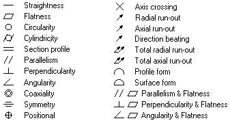
From the drop down list select the desired type of the tolerance:
Specification. This parameter determines how the value of the tolerance will be obtained. You can enter it manually or it can automatically be calculated depending on the dimension’s value and precision.
Expression. Can be one of the following choices:
- not defined; |
|
R |
- if a circular or cylindrical GD&T symbol is defined by the radius; |
D |
- if defined by the diameter; |
Sphere R |
- if a spherical GD&T symbol is defined by the radius; |
Sphere D |
- if a spherical GD&T symbol is defined by the diameter; |
T |
- if the diametrical expression is used for GD&T symbols of Symmetry, Axis crossing, Profile form and Surface form, as well as the positional GD&T symbols (in the case when the positional GD&T symbol is bounded by two parallel lines or planes); |
T/2 |
- if the radial expression is used for the same GD&T symbols as above |
Dimension. Value of the dimension upon which the value of the tolerance depends. If, when setting the tolerance, you tied it with the dimension, then the nominal value of the dimension will automatically be inserted into the parameter’s field. The value of the dimension affects the tolerance’s value in automatic calculation.
Precision. Takes integer values in the range from 3 to 16, inclusive. This parameter makes sense only when using the automatic tolerance calculation.
Value. This is the value of the tolerance, either input manually or calculated automatically. A predefined list of values is supplied for the manual parameter definition.
«Datum» Section
Datum 1, Datum 2 and Datum 3. These are the names of datums that can be used in the GD&T symbol, defined as textual strings. Text variables can be used as datum names just like in the case of any other text string parameters.
«Arrows», «Arrow», «Text on arrow», «Symbol on Arrow» Sections
Next two sections of the properties window – “Arrows” and “Arrow” – should be considered together. Together they allow us to specify parameters of the tolerance’s extension lines.
The “Arrows” section contains the list of all created arrows-extensions of the tolerance. The buttons to the right of the list allow us to create/remove the arrows. By selecting one of the arrows in the list with the help of ![]() , in the next sections of the properties window it is possible to specify parameters of the given arrow.
, in the next sections of the properties window it is possible to specify parameters of the given arrow.

The “Arrow” section contains the following parameters of the selected arrow:
Drop down list for selection of the arrow type at the beginning of the extension line. This list coincides with the list of arrow ends used in the commands for construction of dimensions, graphic lines and leader notes.
Field for specifying the arrow tip size at the beginning of the extension line. If the “From document” value is selected, it will be calculated based on the given parameter «Arrows (end) size» in the command “ST: Set Document Parameters” (the «Line» tab).
Line thickness. Specifies thickness of arrow lines. In case when the value of this parameter is set to «From document», it will be evaluated based on the given parameter «Other lines» in the command “ST: Set Document Parameters” (the «Lines» tab).
Clear under arrow. When this parameter is enabled, the drawing’s image under the tolerance’s arrow is removed.
Clear under line. This parameter allows us to remove the drawing’s image under the tolerance’s arrow line.
Draw extension line. This parameter controls drawing of the extension line for extension of the tolerance, from the snapping point up to the arrow.
Clear under extension line. When this parameter is enabled, the drawing’s image under the extension line is removed.
«View» section
Text after. This parameter allows entering an arbitrary text string that you want to be displayed after the tolerance value. You can enter, for instance, conditions for dependencies, unevenness, etc. Use the key combination <Alt+F9> for this purpose.
![]()
![]()
![]()
![]()
Show dimension’s value. It can take the values “No” and “Yes”. If this parameter has the value “Yes”, then the dimension’s value will be placed after the tolerance’s value. If necessary, in this line use the variables by embracing them into curly brackets.
|
0.01/10 |
Extension line. This parameter is active only upon creation of the tolerance without extension line. It controls the drawing of the extension line from the snapping node/line up to the tolerance.
«Placement» section
Placement. Defines the box positioning with respect to the attachment node. Eight different positioning options are provided in the pulldown menu.
Rotate 90. Can be set or unset. If set, the GD&T symbol will be rotated by 90 degrees.
«Options» section This section contains the following tolerance’s parameters: Show parameters dialog for each element. If this parameter is enabled, then in the tolerance creation command after specifying location of the tolerance on the drawing, the parameters dialog window will automatically appear on the screen (the This mode allows us to work in the same way as in the previous versions of T-FLEX CAD – first specify the tolerance location on the drawing, and then specify the tolerance’s parameter. Create automatically. When this parameter is enabled, the tolerance creation will automatically be completed right after specification of the snapping point of the tolerance’s rectangle (without pressing |
|
Creating Datum
To create a leader or a datum with a leader, use the automenu icon |
|
Similar to the tolerance, at any moment of datum creation it is possible to specify the datum’s parameters in the command’s properties window. The dialog in the command’s properties window contains all main parameters of the datum. To make the work more convenient, the dialog is divided into several sections. Some of the sections – “Coordinates”, “Arrows”, “Arrow”, “Options” entirely repeat analogous sections of the tolerance’s parameters dialog.
The “Datum” section, used for datum creation, contains different, shorter set of parameters compared to the identically-named section in the tolerance’s parameters: Datum. Datum name parameter (text string). For the datum’s name it is possible to use the variable. Location. Defines location of the frame with respect to the snapping node. There are eight different options which are selected from the drop down list. Extension line. This parameter is active only upon creation of the datum without extension line. It controls the drawing of the extension line from the snapping node/line up to the datum. |
|
Editing GD&T Symbol
To edit GD&T/ datum symbol parameters, position, attachment or to set or break the relation between a GD&T/ datum and a drawing dimension, use the command "EFO: Edit GD&T Symbol":
Keyboard |
Textual Menu |
Icon |
<EFO> |
"Edit|Draw|GD&T Symbol" |
|
Upon calling the command, the following icons are available in the automenu:
![]() <*> Select All Elements
<*> Select All Elements
![]() <Esc> Exit command
<Esc> Exit command
You can select a GD&T/ datum symbol by pointing it with the mouse and clicking ![]() , or by using multiple selections. As in the case of other drawing elements, the multiple selections are done by the option
, or by using multiple selections. As in the case of other drawing elements, the multiple selections are done by the option ![]() . Using
. Using ![]() together with the pressed key <Shift> adds an element to the list of selected ones, while with the pressed key <Ctrl> - removes from the list of selected elements.
together with the pressed key <Shift> adds an element to the list of selected ones, while with the pressed key <Ctrl> - removes from the list of selected elements.
For multiple selections, you can use the options:
![]() <P> GD&T Formlimit Parameters
<P> GD&T Formlimit Parameters
![]() <Alt+P> Copy properties from the existing element
<Alt+P> Copy properties from the existing element
![]() <Del> Remove selected elements
<Del> Remove selected elements
![]() <Esc> Cancel selection
<Esc> Cancel selection
When selecting one element, the following icons become available in the automenu:
![]() <P> GD&T Formlimit Parameters
<P> GD&T Formlimit Parameters
![]() <Alt+P> Copy properties from the existing element
<Alt+P> Copy properties from the existing element
|
<M> |
Select linked dimension |
|
<Ctrl+M> |
Break tie with dimension (only upon selection of the element tied with the dimension) |
|
<Space> |
Add arrow |
|
<Del> |
Delete arrow |
|
<I> |
Select Other Element |
|
<Del> |
Remove selected elements |
|
<Esc> |
Cancel selection |
To change location and snapping of the tolerance/datum, it is necessary, after element selection, indicate the marker of the desired snapping point with the help of ![]() . The selected point will start dynamically follow the cursor (according to the snapping method selected for the point). At the same time the additional options will appear in the automenu:
. The selected point will start dynamically follow the cursor (according to the snapping method selected for the point). At the same time the additional options will appear in the automenu:
|
<T> |
Link to node |
|
<K> |
Break (kill) relations |
|
<F> |
Snap to arrow (available only upon selection of the second snapping point of the note) |
|
<U> |
Orthogonal Fixing/Fixing to point/Angle Fixing |
|
<L> |
Set relation with line |
|
<N> |
Select node |
|
<D> |
Set relation with dimension |
Pressing ![]() will fix the new location of the snapping point of the tolerance. It is possible to change location of any bend point exactly in the same way. It is also possible to cancel snapping of the point with the help of the
will fix the new location of the snapping point of the tolerance. It is possible to change location of any bend point exactly in the same way. It is also possible to cancel snapping of the point with the help of the ![]() option, snap tolerance to a node or line, specify/cancel relation with dimension.
option, snap tolerance to a node or line, specify/cancel relation with dimension.
To remove one of the arrow-extensions of the tolerance, it is possible to use the ![]() option. If the tolerance/datum being edited has only one extension, then this option is available in the automenu right after selection of the element being edited. In case if the tolerance/datum with several extension lines, the
option. If the tolerance/datum being edited has only one extension, then this option is available in the automenu right after selection of the element being edited. In case if the tolerance/datum with several extension lines, the ![]() option will become available after selection of the desired extension line. The extension line can be selected in the command’s properties window (the “Arrows” section) or, for example, by specifying its starting point in the drawing’s window. To remove the extension line, it is also possible to use the
option will become available after selection of the desired extension line. The extension line can be selected in the command’s properties window (the “Arrows” section) or, for example, by specifying its starting point in the drawing’s window. To remove the extension line, it is also possible to use the ![]() button next to the list of arrow-extensions of the tolerance/datum in the command’s properties window.
button next to the list of arrow-extensions of the tolerance/datum in the command’s properties window.
The option ![]() allows modifying the parameters of the selected GD&T symbol notations. Modifying the parameters in the case of a single selected element is similar to original defining of the GD&T symbol parameters.
allows modifying the parameters of the selected GD&T symbol notations. Modifying the parameters in the case of a single selected element is similar to original defining of the GD&T symbol parameters.
In the case of multiple selections, calling the option <P> brings up the dialog box "GD&T Formlimit Parameters". All parameters of the selected elements are subject to editing.
The option <D> allows setting the relation between the selected GD&T symbol and the desired drawing dimension. To delete the selected GD&T symbol, press the key <Del>. To select and modify parameters of a group of GD&T symbols, use the same techniques as for other elements.