Local Section View


Local Section View |
|
The command can be called in one of the following ways:
Icon |
Ribbon |
|---|---|
|
Draw > Projection > Local Section View Assembly > Additional > Local Section View Sheet Metal > Draw > Local Section View Weld > Additional > Local Section View |
Keyboard |
Textual Menu |
<3DJ> |
|
It is also available as option in the 2D Projection command:
|
<4> |
Local Section View |
This command allows creating local section views on an existing projection.
The boundaries of the local section view are defined by the hatch contour. You can use an existing hatch or create a new one directly in the Local Section View command.
Use the following automenu option to select an existing hatch:
|
<1> |
Select Hatch as boundary of local section view |
Upon completing creation of the local section, the hatch becomes invisible, while screening out a portion of the main projection. The lines of the local section will be drawn with higher priority, than those of the hatch and the main projection.
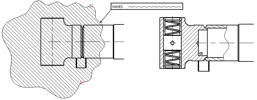
Geometry of the graphic lines bounding the contour of the original hatch can be taken into consideration when defining the boundaries of the local section view. For example, if the hatch contour pattern was set as waves, the boundaries of the local section view will also have waves pattern. A user can toggle on/off the lines type switch found in the parameters of the local section view.
Use the following automenu option to create a new hatch directly in the Local Section View command:
|
<6> |
Create Hatch by Spline |
Upon selecting this option, click  on a drawing sheet.
If cursor is inside boundaries of any existing projection (the projection gets highlighted in this case) at the moment of clicking , then the spline command will be launched:
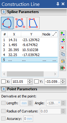
Upon finishing spline creation, the system returns to local section view command and selects this spline as a section boundary.
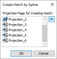
If cursor is outside boundaries of any existing projections at the moment of clicking , then the projection selection dialog appears. Upon selecting a projection, the system launches the same spline command as described above.
Next, define the position of the section plane. The plane normal automatically coincides with the viewing direction of the main projection – the one used for creating the local section view. Thereafter, position the view plane either by a 3D node or by a 2D node in another projection. For example, if you are creating a local section on the Left View, then the 2D node can be selected in one of the adjacent standard views: Front, Top, Bottom, Back.
The 2D or 3D node can be selected using the options:
|
<3> |
Select 3D Point, defining section position |
|
<2> |
Select 2D Node on other Projection, defining section position |
The local section view is automatically tied to the projection on which it was created. However, this tie needs to be broken in some situations, in order to attach the local view to the drawing at a different location. The option to break the tie is:
|
<K> |
Set / Break link with projection |
Once the tie is broken, the following option is available for attaching the projection to the drawing (an unconstrained attachment or snapping to a 2D node).
|
<5> |
Move Local Section View |
When creating a local section view, we recommend selecting specific model elements to be projected. Selecting the elements that actually fall in the area of the local section view speeds up regeneration of the projection.