Model configurations and variations


Model configurations and variations |
|
General Information
Configuration – saved in the document additional version of the model’s geometry satisfying several given conditions. Geometry of configurations is not shown in the 3D scene of the document.
By default, the T-FLEX CAD document stores only the geometry corresponding to the last saved state of the 3D model of the given document.
The main domain of application of configurations is for design of 3D assemblies. Geometry saved in the configuration can be inserted into the assembly instead of the actual geometry of the fragment. The use of configurations allows the user to rapidly download the required version of the fragment without additional recalculation and transformation of fragment’s model.
Variation is a special configuration type intended to work with the product structures. The variations are used for variant BOMs creation.
More information about variant BOMs can be found in “Product structures, reports and BOMs” chapter.
T-FLEX CAD document can contain any number of configurations. Each configuration is assigned the unique name.
Depending on conditions defining the saved configuration, configurations can be divided into 2 types:
-Configurations by a total collection of bodies – store the geometry of all bodies of 3D model;
-Configurations by optional collection of bodies – store the geometry of an optional collection of bodies corresponding to any operations and Bodies from the model’s tree.
If the document contains external variables, in each configuration a collection of values of external variables is also stored, for which the geometry of configuration was calculated.
Configurations can be also created in the 2D documents. In this case, configuration is capable to store only collection of values of document’s external variables. Such configurations can be used while working with 2D fragments for quick specification of values of fragment’s variables.
Using Configurations
When inserting a document with configurations as a 3D fragment, as usual, it is possible to either specify the values of external variables of fragment required in the assembly (if a fragment has them) or specify one of the configurations saved in the document.
When specifying the values of variables, the system has to recalculate the entire model of the fragment according to the values specified in the assembly. The geometry obtained as a result of recalculation is put into the assembly.
When using configuration (created in the document of a fragment in advance), recalculation of the fragment’s model is not carried out, - the geometry stored in the configuration is inserted right away. Geometry inserted into the assembly contains only the bodies which were saved in the configuration.
Since there is no recalculation of the fragment’s model upon insertion of configurations, the time spent on assembly construction is significantly reduced. This is especially evident when inserting the fragments containing quite complicated constructions and the large number of operations. The possibility to control the structure of the geometry saved in the configuration provides even wider capabilities for design of 3D assemblies.
Mechanisms, purpose and operation with the first and second types of configurations are considerably different, thus, a separate description of each is required.
Configurations by a total collection of bodies
When creating configuration by a total collection of bodies the user specifies only the values of those external variables of the document to which geometry of the configuration has to correspond. Geometry of all final bodies of the 3D model is saved in the configuration.
The use of configurations of this type for 3D fragments allows the user to avoid the recalculation of fragment’s model in the assembly. To take advantage of this capability, upon the fragment’s insertion, instead of entering the values of the variables, the user needs to specify one of the configurations of the fragment. Geometry of the indicated configuration will be downloaded into the assembly.
The system can use the geometry from the configuration of the fragment automatically. This happens when for 3D fragment the user specifies the values of the variables coinciding with the set of values for one of the configurations of the fragment. If this coincidence takes place, then instead of recalculation of the fragment’s model, the system downloads the geometry from the corresponding configuration. Note that this rule is valid only for configurations by a total collection of bodies.
Configurations by optional collection of bodies
When creating configuration by an optional collection of bodies, in addition to a collection of values of external variables, any arbitrary set of operations and Bodies from the model’s tree of the document is specified. The geometry that will be stored in the configuration represents a collection of all selected operations/bodies. When using the current document as a fragment, such configuration will be inserted as a multi-body fragment.
Multi-Body fragments can be automatically divided into several separate bodies, if, in the properties of the fragment in the assembly, the parameter “Use” (tab “Operation”) is assigned the value “As separate bodies”.
Insertion of configuration by an optional collection of bodies into the assembly can be carried out only by explicit specification of the name of the required configuration in the fragment’s properties.
Configurations by an optional collection of bodies can be used in cases requiring different representation of the model’s geometry in the fragment and in the assembly. For example, inside the assembly they allow displaying the bodies corresponding to the operations in the middle of the model’s tree of the fragment. Example – the parts with completed finishing of welded joints. Finishing of welded joints requires creation of a large number of additional operations complicating the model and increasing the recalculation time. In the 3D model of the part itself, the finishing of welded joints is necessary, but in the assembly it is often unnecessary and significantly burdens the assembly model. In such situation in the fragment it is possible to create configuration containing the part’s geometry without finishing of welded joints. The list of bodies stored in this configuration will consist from one operation which precedes the operations simulating the finishing of welded joints. If, upon the insertion of the fragment into the assembly, the user selects this configuration, the part will be displayed in the assembly without finishing of welded joints.
Configurations can be also used for fragments whose structure must be modified from one assembly to another. For example, assume that the fragment’s model contains a collection of bodies, but it is required to include only some of them into different assemblies, and, moreover, in different combinations. In this situation, in the fragment’s document the user can create several configurations with different collection of stored operations, and download them into the assemblies as needed.
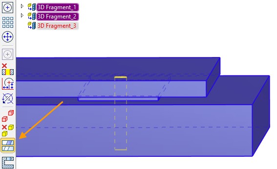
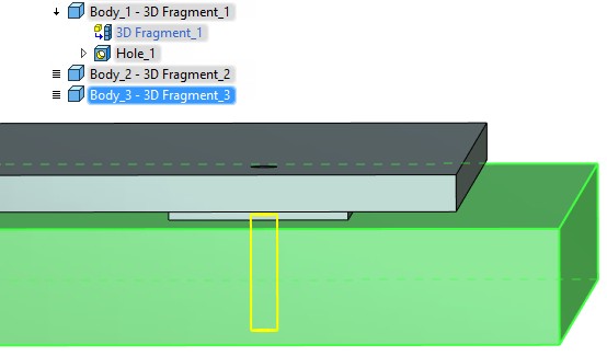
As another example of the use of configurations consider the following: often, in the assembly the user needs to create a hole adjusted for a non-standard part, and then insert, as a fragment, the part itself. To do that, in the document of the fragment-part the user can create configuration storing a simplified state of the model (operation from the middle of the model’s tree) and a final view of the part (operation from the top of the tree or a Body). When inserting such configuration into the assembly with the use of fragments’ partitioning into the bodies one of the inserted Bodies can be used for creating a hole (with the help of Boolean operation of subtraction), another Body – for obtaining the fragment-part itself.
Creating and Editing Configurations
For creating and editing configurations the command “FCE: Edit Model Configurations” is used:
Icon |
Ribbon |
|---|---|
|
Parameters → Tools → Configurations and variations |
Keyboard |
Textual Menu |
<FCE> |
Parameters > Model Configurations and variations |
This command can be unavailable if the current document was not saved.
Calling the command brings up the dialog box for managing configurations of the current model:
Option ![]() Create configuration is used to create a new configuration. Option
Create configuration is used to create a new configuration. Option ![]() Create variation is used to create a new variation. A new name may be assigned for the new configuration or variation.
Create variation is used to create a new variation. A new name may be assigned for the new configuration or variation.
You can specify a product structure type for the new variation. It is recommended to select Variant BOM if you plan to create a variant BOM table subsequently.
If the field “Part No.” is filled, it will be set as configuration/variation name by default. If it is empty, the current document name will be used. The product structure will be automatically created after the variation saving. Its name matches the source name. For already created configurations/variations, you can change the name and, if necessary, specify the subtitle by editing the corresponding cell in the table. |
|
The set of variable values that corresponds to the current state of the model is assigned for a new configuration/variation, by default.
There are following options in the context menu:
Change type to “configuration”/”variation” allows to switch type of currently selected element.
Sort by name allows to activate sorting by Name column.
Delete product structure deletes product structure for the currently selected element. You can reassign the product structure in the Product Structure window by clicking “Create…”
![]()
Base variation. The flag to the left from the name is used for the base variation selection.
|
The properties of product structure corresponding to the base variation are used for data display in the Product Structure window in the Apply product structure representation mode. If the flag is not set for any variation, the first variation in the list is considered to be the base. |
|
For selected configuration, the list of external variables values is shown in the table Variables in the upper right pane of the command’s window. The values of variables can be modified in the table. Upon modifying any external variable, the earlier saved configuration becomes outdated and is marked by an asterisk. |
|
|
You need to save changes using option ![]() to make them actual. Some external variables can be deleted, and some can be created when you edit the model.
to make them actual. Some external variables can be deleted, and some can be created when you edit the model.
The “State” column displays information about each variable in configuration. It shows if a variable exists in the model and if the model variable exists in the configuration.
At the lower right pane, there is a list of operations and Bodies of the model, stored in the selected configuration.
“All operations” value is displayed in the list after creating configuration. If the configuration creation is completed at this stage, configuration by a total collection of bodies will be created. Uploaded operations and bodies configuration by an optional collection of bodies is created when you add elements to the list. For filling in the list, you need to set a desired filter in parameter Select: Bodies or operations. After that, it is possible to select any Bodies or operation in the 3D scene or in the tree of the 3D model.
Buttons ![]() and
and ![]() allow you to edit the list of bodies in the configuration:
allow you to edit the list of bodies in the configuration:
-![]() – removes operation/Body selected in the list;
– removes operation/Body selected in the list;
-![]() – removes the entire contents of the list (the list content is replaced with “All operations”).
– removes the entire contents of the list (the list content is replaced with “All operations”).
The following graphic buttons are used for managing configurations as well:
![]() Apply changes – saves changes and new configurations/variations.
Apply changes – saves changes and new configurations/variations.
![]()
![]() Copy/Paste - allows to copy or create a new configuration/variation based on the existing one. You need to specify name for the new configuration. The variables values and the product structure type are copied from the source object.
Copy/Paste - allows to copy or create a new configuration/variation based on the existing one. You need to specify name for the new configuration. The variables values and the product structure type are copied from the source object.
![]()
![]() Move up/Move down - allows to change elements order in the list. The order is important only for the variations. Their order in the variant reports matches the order in the list.
Move up/Move down - allows to change elements order in the list. The order is important only for the variations. Their order in the variant reports matches the order in the list.
![]() Load - regenerates model with a variable values defined in the selected configuration. This command allows viewing geometry of each configuration.
Load - regenerates model with a variable values defined in the selected configuration. This command allows viewing geometry of each configuration.
![]() Update - assigns current values to the external model variables in the current configuration/variation.
Update - assigns current values to the external model variables in the current configuration/variation.
![]() Delete - deletes the selected configuration/variation.
Delete - deletes the selected configuration/variation.
![]() Delete all - deletes all configurations/variations.
Delete all - deletes all configurations/variations.
![]() Create new variations table – creates variation table of the model.
Create new variations table – creates variation table of the model.
You can find more information about variation tables in “Drawing title block” chapter.