Materials


Materials |
|
A material is a T-FLEX CAD element. It contains a list of characteristics of a real material with which we deal in reality. A material is used as a parameter for all 3D operations, and, additionally, by a special command of applying material to individual faces.
Material characteristics can be roughly divided into two types. Characteristics of the first type affect the appearance of three-dimensional objects in the 3D window, and, additionally, define the parameters of a material as part of generating a photorealistic image in the POV-Ray system. Characteristics of the second type are various physical-mechanical parameters of a material, such as density, elasticity coefficient, etc. Those parameters are taken into the account when calculating mass-inertia properties, as well as conducting structural computations in the analysis module. Besides that, materials are accounted for when creating hatches on sections of 3D models. You can define parameters of such hatch for a particular material.
General Information
For each model we can associate a set of materials that were assigned to Bodies, operations or individual faces. These materials are called the materials of the current model. Material – is a 3D element containing a set of characteristics of the real material with which we are dealing in reality. The element “material” has parameters such as density, reflection power, absorbing capacity, etc.
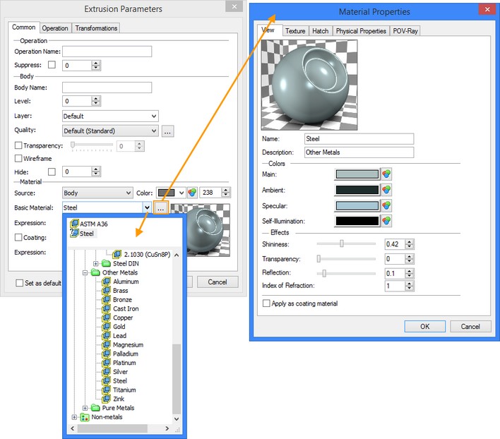
For any Body of the model it is possible to specify the basic material and cover material.
The basic material is used for calculation of mass-inertial characteristics and engineering analysis, and also for displaying the Body in 3D scene in the visualization mode “Shading with materials” (if the additional material of the cover is not specified).
The cover material – is an additional material for defining parameters of the model display in the 3D window. It allows us to specify the material different from the basic one to be used for visualization purposes, creating the effect of the Body “painting”. At the same time for engineering calculations the basic material will still be used.
|
Coating Material
Basic Material |
The material can be applied on individual faces of the body. When the face’s geometry is changed as a result of further transformations of the model the material that was applied onto the face is retained. When applying the material on individual faces, the body itself does not change its own material. You can apply material on individual faces only when the flag “Apply as coating material” is enabled.
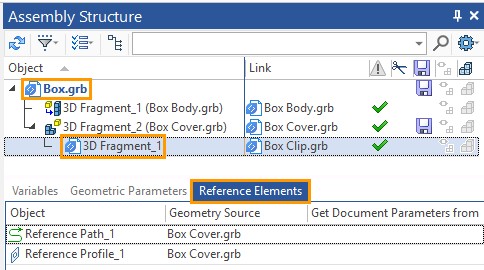
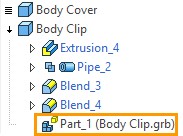
Materials used in the current model are displayed in the tree of the 3D model, in the operations properties dialogs, and in the dialog of the “3MТ: Edit materials” command.
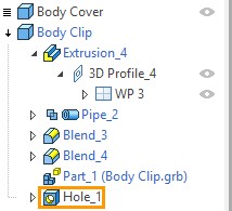
Materials in tree of 3D model
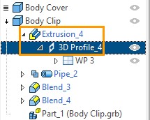
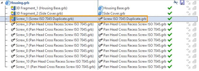
Materials used in the current model are displayed in the tree of a 3D model in the special folder – “Materials”.
Different icons are used in 3D model tree to identify coating and basic materials.
The icon ![]() is used to identify coating material. The icon
is used to identify coating material. The icon ![]() is used to identify basic material.
is used to identify basic material.
If the material is applied to any body in scene, the icon ![]() appears to the left of the materials name. If you press this icon, the list of objects to which the material is applied will appear. Icon do not appear near not applied materials.
appears to the left of the materials name. If you press this icon, the list of objects to which the material is applied will appear. Icon do not appear near not applied materials.
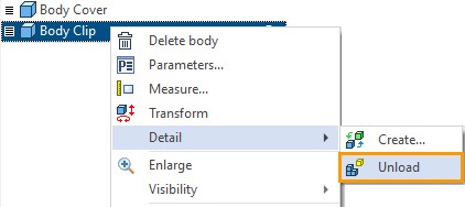
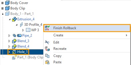
It is possible to edit material properties or delete the material from the current model using 3D model tree. The commands for deleting and editing the material properties are available in the context menu of the 3D model tree.
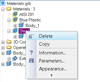
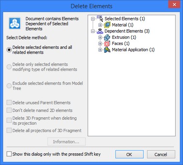
Note that upon deletion of the applied material, the system will also prompt you to delete the operations to which the given material was applied.
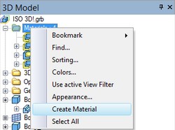
If necessary, the user can create the new materials directly in the tree of the 3D model by activating the command of the context menu “Create Material”. After that the material properties dialog appears on the screen.
Service window “Materials”
Special service window – “Materials” is used to work with materials. It is available even if there is no open document.
To display this window, the following commands can be used:
Keyboard |
Text menu |
Icon |
|---|---|---|
<Alt+8> |
«Customize|Tool Windows|Materials Window» |
|
<3MT> |
«Tools|Materials» |
|
This command can also be invoked by pressing ![]() in the domain of automenu or of any toolbar.
in the domain of automenu or of any toolbar.
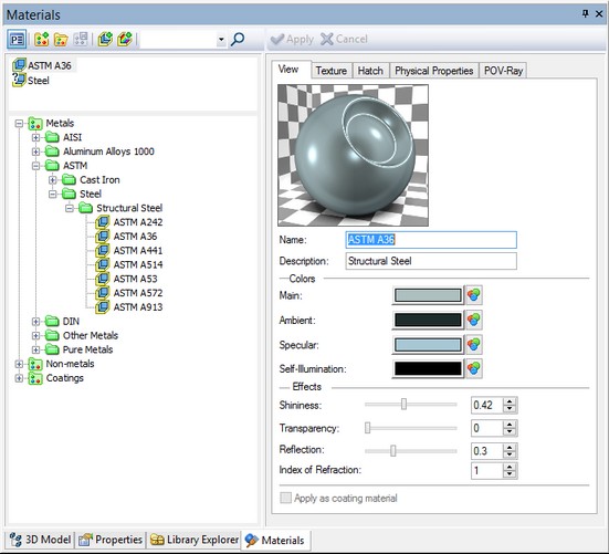
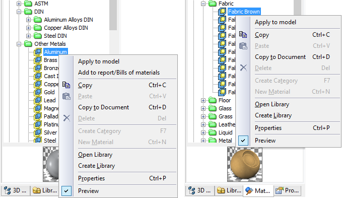
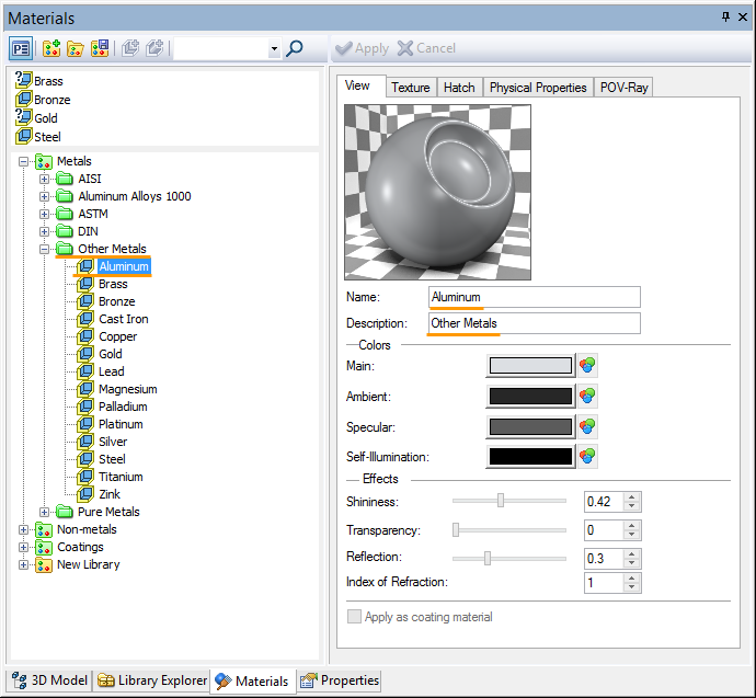
The “Materials” window is divided into three parts: current model materials, material libraries and preview.
The current model materials are displayed in the upper part of the window. By default, the list contains one element – “Steel”.
Material libraries are displayed in the middle part of the window. All opened libraries are listed here. There are three libraries that are opened by the default: Metals, Non-metals and Coatings.
Preview window is displayed in the lower part.
On the top of “Materials” window there is a special toolbar. It is used to work with materials and material libraries.
|
Materials Toolbar
Current Model Materials |
Material Libraries |
|
Preview |
Materials Toolbar Options
To view/edit the material’s properties it is required to select the material (in the list of materials of the current model or in the library) and press the button ![]() in the upper part of the window or press
in the upper part of the window or press ![]()
![]() . If the window is “fixed”, a separate dialog window of parameters of the selected material will appear.
. If the window is “fixed”, a separate dialog window of parameters of the selected material will appear.
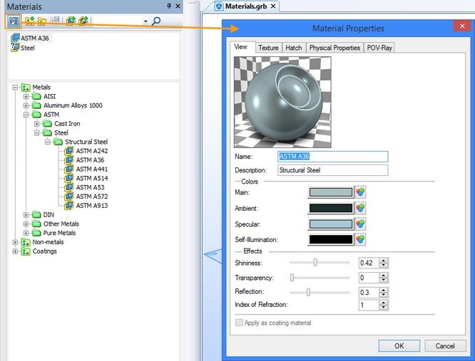
When the “Materials” window is in “floating” mode, the dialog of parameters of the selected material will appear in the right part of the “Materials” window itself. The dialog of parameters can be hidden by pressing ![]() again.
again.
The same dialog window can be invoked from parameters of any 3D operation or Body with the help of the ![]() button. This button is located on the «Common» tab.
button. This button is located on the «Common» tab.
The option «Create material» ![]() allows you to create a new material. Material is created either in the current model or in the library, according to the currently selected part of the window.
allows you to create a new material. Material is created either in the current model or in the library, according to the currently selected part of the window.
The «Create color-based material» option ![]() allows us to create the cover material based on color. After activation, the dialog for selection from the colors catalog appears.
allows us to create the cover material based on color. After activation, the dialog for selection from the colors catalog appears.
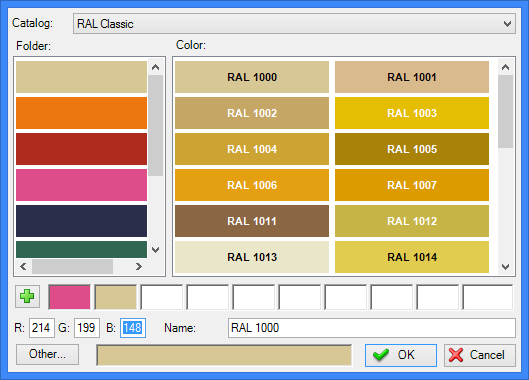
After selection of the color the new material is assigned the same name as the selected color (for example, “RAL 1000”). After confirming color selection, in the current window of the materials library or of the model the cover material is created with the corresponding name and properties.
The flag “Apply as coating material” is automatically set for a created coating material.
To navigate across the material libraries you can use search toolbar. With its help, the material can be found by the name or by part of the name.

|
For searching, you need to enter the name of material or part of its name into the text field or select the material from the drop-down list, if it already exists in the search field. After pressing <Enter> or The search among materials of the model is not carried out. The remaining icons in the upper part of the “Materials” window are designed for working with the materials libraries. |
The ![]() option allows us to create the new user-defined library of materials. The library is highlighted with green color
option allows us to create the new user-defined library of materials. The library is highlighted with green color ![]() , if it is located in system readonly folder. If library is located in any non-system folder and can be edited, it is highlighted with yellow icon
, if it is located in system readonly folder. If library is located in any non-system folder and can be edited, it is highlighted with yellow icon ![]() .
.
The option “Open library” ![]() serves for opening already existing materials library. After activation, you need to specify a path to the library file.
serves for opening already existing materials library. After activation, you need to specify a path to the library file.
The option “Save changes in libraries” ![]() allows us to save the changes introduced into the materials library.
allows us to save the changes introduced into the materials library.
More information about working with libraries of materials can be read below.
Materials of the Current Model
The list of the current models materials provides quick access to the most frequently used materials without searching through the libraries. It contains all materials that were used in the current document.
To identify coating materials icon ![]() is used. To identify basic materials icon
is used. To identify basic materials icon ![]() is used. To identify materials that were applied previously but not in use, there is icon
is used. To identify materials that were applied previously but not in use, there is icon ![]() .
.
The following actions can be executed with the list of materials of the current model:
●Edit materials (The “Properties” option in the context menu);
●Add information about material into report and BOMs (The “Add to reports/Bills of materials” option in the context menu);
●Add new materials (the “Create Material” option in the context menu);
●Remove materials from the model (the “Delete” option in the context menu);
●Copy materials from the library to the list of materials of the model, from one T‑FLEX CAD document to another (the “Copy”, “Insert” options in the context menu):
●Enable/disable preview option.

Materials libraries
The list of material libraries is an archive with basic and coating materials that are most frequently used in design. These materials are sorted by categories. There are three libraries that are opened by the default: Metals, Non-metals and Coatings. They are identified by ![]() icons.
icons.
Materials from these libraries can’t be changed inside the libraries. For this purpose, they should be moved into Current model materials window or into created library.
The obsolete libraries of previous T-FLEX CAD versions are also available and can be opened if necessary.
For various operations with libraries and materials you can use commands from right button context menu of “Materials” window or materials toolbar.
Material Libraries Creation
You can create your own libraries with customized set of materials.
For this purpose, use option ![]() on the materials toolbar or item “Create Library” in context menu. The user-created library is identified by icon
on the materials toolbar or item “Create Library” in context menu. The user-created library is identified by icon ![]() . The newly created library appears in the list of available libraries and has the default name "New Library".
. The newly created library appears in the list of available libraries and has the default name "New Library".
Material can be created only in custom library open for editing. You cannot create material in system readonly folders identified with ![]() icons.
icons.
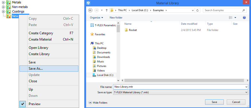
The newly created library is not saved by default. In order to make the library available in future, use option ![]() on the materials toolbar or item “Save as…” from the context menu. You can rename library and set new folder location before saving. Files in T-FLEX CAD are saved in .mtr format.
on the materials toolbar or item “Save as…” from the context menu. You can rename library and set new folder location before saving. Files in T-FLEX CAD are saved in .mtr format.
File in .mtr format can be opened in any text editor.
To open a library use option ![]() at the materials toolbar or item “Open Library” from the context menu.
at the materials toolbar or item “Open Library” from the context menu.
All material libraries are located in folder “Program\MaterialLibrary” by default. The path is displayed when you put the cursor on the library name.
In a case, when changes in library were not saved before closing, system will offer you to save these changes.
Catalogs of Materials Creation
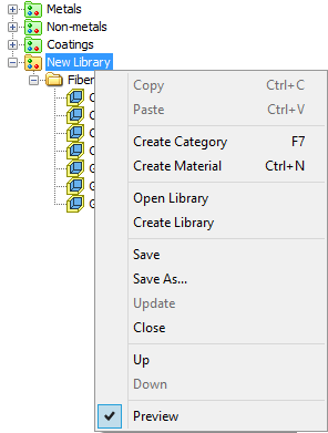
For convenience, you can combine materials within the separate catalogs for each group of materials. To create a new catalog you need to select library, in which it will be created, press ![]() and select item “Create catalog” from the context menu. Created category will be called “New Catalog”. You can rename catalog directly after creation or rename it later using item “Rename” from the context menu.
and select item “Create catalog” from the context menu. Created category will be called “New Catalog”. You can rename catalog directly after creation or rename it later using item “Rename” from the context menu.
Created category can be deleted using item “Delete” from the context menu.
![]()
![]()
To copy all materials from a catalog to the list of materials of the current model, use command “Copy to Document” from the context menu or drag the category manually.
Within one library, you can create any number of catalogs. In each catalog, you can create additional folders with materials (sub-catalogs). The catalog can be copied and transferred to another library or catalog. |
|
Materials Creation and Applying
To create a material in the new libraries and catalogs, use command New Material or options ![]() and
and ![]() on the materials toolbar.
on the materials toolbar.
To apply a material to objects in the scene, you can use item Apply to model from the context menu or "drag&drop" method.
If there are several bodies in the scene, the following dialog window appears:
If you press OK or if there is just one body in scene, the following window appears:
Add to Report/Bill of materials allows to add information about material into reports and bills of materials.
In case, when changes in one or several materials from library were not saved before closing, system will offer you to save these changes.
To move materials within a library or from one library to another or between catalogs and lists of materials of the current model you can also use "drag&drop". The individual materials can be copied, using the context menu commands Copy and Paste.
If the material or catalog is copied to a material library or catalog that already contains an element with the same name, the copied item will be automatically renamed and numbered with (1), (2) and so on suffix.
Preview
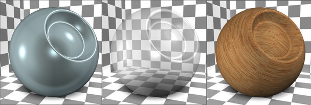
The preview window allows to estimate material visually, without applying it to the objects in the scene. The mode is activated by item Preview from the context menu.
![]()
Selected material can be displayed on the cubic or spherical surface. To switch between these modes click ![]() on the picture.
on the picture.
Change Material Using Variables
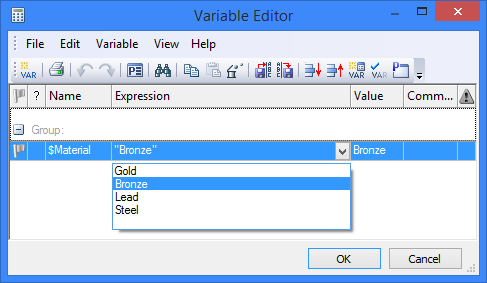
Variable can be used to assign material names. For that purpose you should use existing or create a new text variable using command: “V:Edit Variables”.
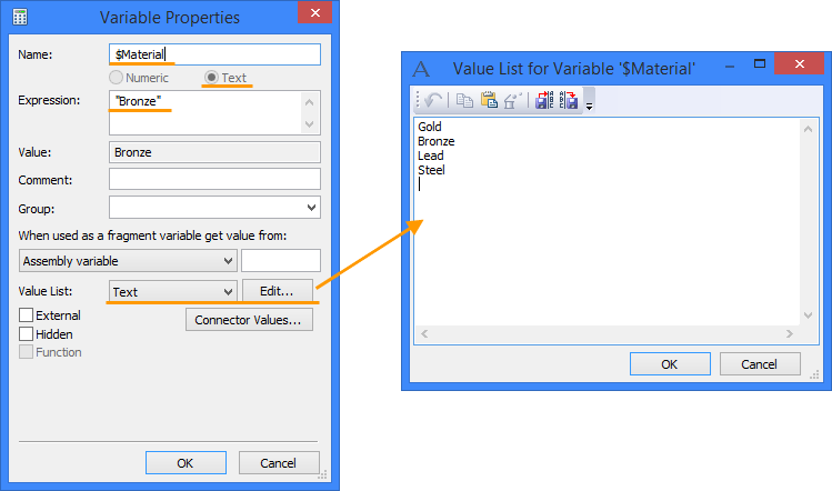
In the expression field, you should enter or copy from the library the name of the material that will be used for the model.
In order to generate a list of several items you need to use the [Edit...] button. In the window "Value List for Variable" you need to specify all materials that can be used for this model. It is important that the names of materials must match similar names in the library.
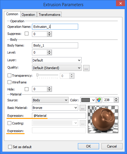
After creation of the variable you need to enter the properties of the body, and set the name of the created variable in the field "Expression". Thus you can set main material and coating material.
After completing these steps, you can change the material of one or more bodies with the drop-down list in the variables window.
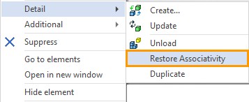
To display the new material in the scene, you need to update the 3D model using the option ![]() .
.
Material’s properties dialog
The material’s properties dialog contains all physical-mechanical properties of the material, displays parameters of the material in 3D scene and on projections, and parameters for creation of photorealistic image (see the «Photorealistic view» chapter).
To call properties dialog window you need to select material (in the current model materials list or in the library) and perform one of the following actions:
- press ![]() icon on the materials toolbar
icon on the materials toolbar
- press ![]()
![]() on the material name
on the material name
- select item Properties from the context menu.
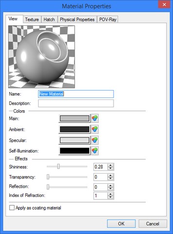
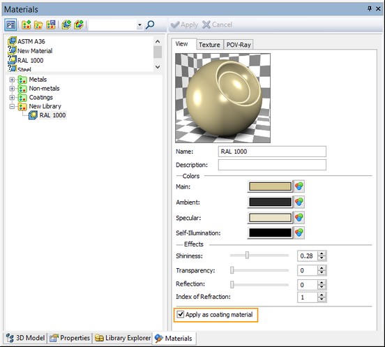
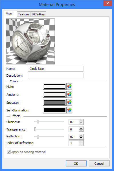
«View» Tab
This dialog combines parameters controlling characteristics of color, reflection, transparency and material’s light emission.
The image of the material on this tab is available in two versions: in the form of a sphere with a hollow or in the form of a cube, for a more complete display of the visual characteristics of the material.
Name. In this field, material name can be edited.
Description. This field displays the name of folder containing material.
For the model material this field can be edited so you may enter your own description.
When copying material to a library, description will be named by folder name where it is placed.
«Colors» Group
This group combines parameters defining characteristics of material’s color. To specify the color for one of the parameters, it is required to click into the color rectangle and use the standard mechanism for color selection.
Main. This parameter controls the color of the material lighted up by direct light. This is a base color of the material.
Ambient. This parameter controls the color of the material lighted up by dispersive light. It significantly affects the color of the material’s surface since at the given moment of time only a small portion of object is subject to the action of direct light.
Reflecting (blink). This parameter controls the color of blinks that appear on the surface of object. The brighter the color, the more intensive the blink is.
Light Emission. This parameter controls the intensity of the light radiated by the material. If the material does not radiate the light, the black color is specified.
«Effects» Group
This group of parameters allows us to customize the following optical characteristics of materials:
Shininess. This parameter controls the power of reflection of light sources on object’s surface. It is specified as a single number that can range between 0 (minimum) and 1 (maximum). Large values create the appearance of smoother and shinier material whereas the decrease in their values imitates dull surfaces.
Transparency. This parameter controls the value of transparency of the object’s surface. It changes between 0 (nontransparent surface) and 1 (totally transparent surface).
Reflection. This parameter controls the value of the specular reflection of the material. It is specified as a number in the range between 0 (reflections of surrounding objects will not be shown on the material’s surface) and 1(entire reflectivity of the material is provided).
Index of refraction. This parameter characterizes the deflection of light rays as they pass through the transparent material. Using the index of refraction you can set the value of this parameter for a transparent material. This option is taken into account when generating photorealistic images.
If the «Apply as cover’s material» parameter is enabled, the material is applied as a cover’s material and not as the basic material. |
|
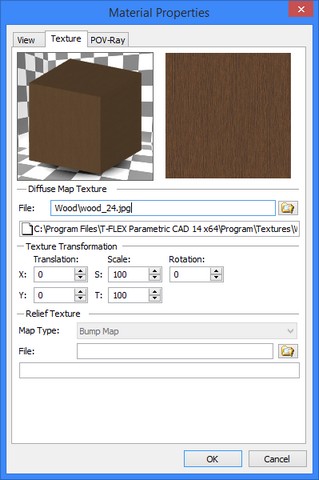
«Texture» Tab
This tab combines parameters that control the material’s texture specification. Texture – is an image that is stored in the file and helps us to display special features of material’s surface coloring.
File. File of the image containing the picture of the texture. To specify the texture, the files of the formats bmp, gif, jpg, jpeg, tga, tif, tiff and png can be used. The work with texture files is realized according to the general algorithm of working with references to external files (similar to fragments, pictures, files of databases by reference etc.). This means that: 1.Texture files can be located in the same folder as the model’s file that uses this texture; 2.Color texture and relief texture can be specified by different files; 2. Texture files can be moved with the “Move assembly” command similar to other types of files; 3. Texture files can be included into the file of the model that uses the texture (embedded textures); 4. To specify the path to the texture file the library’s name can be used; 5. To specify the path to the texture file, the relative paths that includes the folders names or transition to the upper level (..\) can be used.
|
|
When you choose texture file folder “Program\Textures” is opened by default.
«Texture transformation» group
This group of parameters serves for customizing the appearance of the texture, translation of the texture, changing its scale and for rotation.
Shift X. This parameter defines the shift of the texture’s start point along the horizontal axis.
Shift Y. This parameter defines the shift of the texture’s start point along the vertical axis.
Scale S. Texture’s scale along the horizontal axis. The scale’s value can be negative. If, for example, we specify the value «−100», the texture will be symmetrically reflected with respect to the horizontal axis.
Scale Т. Texture’s scale along the vertical axis. The scale’s value can be negative.
Rotation. Texture’s rotation angle. The texture is rotated around the center located in the plane perpendicular to the direction of texture’s projection. The coordinates of the rotation center in the plane are specified by the parameters «Center S» and «Center T».
«Relief texture» group
This parameter group is responsible for creating the visual relief of surface material. The essence of the feature is that by adding shadows and highlights we get effect of the surface material relief.
There are three main ways for creating effect of relief surface corresponding to texture type:
![]()
●Normal Map. This texture like bump map allows to simulate bumps and roughness of the surface. This texture more accurately renders surface relief compared to bump map texture. It is set by default.
●Bump Map. This texture allows you to create the illuminated and shaded areas to simulate simple bumpy surfaces, flat protrusions or dents.
●Parallax Map. If you use this texture surface relief becomes three-dimensional and looks differently from various angles.

File. File of the image containing the picture of the texture’s relief. To specify the texture it is possible to use the files of bmp, gif, jpg, jpeg, tga, tif, tiff и png formats.
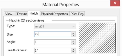
«Hatch» tab
When creating sections and cut views in the «3J: Create 2D projection» command there is a capability of automatic hatching of the section. Hatching used in the section is defined with the following parameters: Type. Hatching type. Size. Distance between the neighboring hatching lines. Rotation angle. Angle of rotation of hatching lines. When selecting the hatching, the tilt angle of 0 degrees signifies the hatching with horizontal lines Line thickness. Parameter allows to specify the thickness of lines. |
|
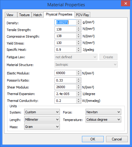
«Physical properties» tab
In the window of this dialog, you can specify physical-mechanical properties of the material. These parameters are used in calculation of mass-inertial characteristics and also when performing structural calculations in the analysis module.
In the upper part of this window, the physical-mechanical properties can be specified. In the lower part of the window, the units of measurement can be selected. When changing the parameters of the units of measurement, the values of physical-mechanical properties are recalculated automatically. You can specify the physical-mechanical properties with variables. |
|
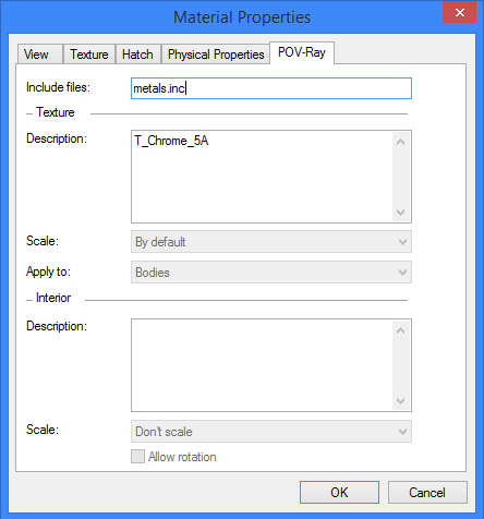
«POV-Ray» tab
In the window of this dialog, you can specify parameters that are used upon creation of photorealistic view (see the «Photorealistic view» chapter). In POV-Ray tab, a large number of characteristics of surfaces and inner space of bodies are used for description of the 3D scene. All materials from the materials libraries supplied with the system already have the POV substitutions (libraries from POV-Ray, for example, textures.inc, are used in them). In the «Material POV» window, the following parameters can be specified: Include files. The field of the given parameter shows the files in which available characteristics for the specified material are stored. |
|
“Texture” group
Properties of the body surfaces are specified in this group.
Description. Name of texture that is specified in one of the included files is displayed in this field. Here you can specify custom properties if you know POV-Ray programming language.
Scale. Defines way of displaying for the specified texture, when applied to a body.
Don’t scale. The specified texture will repeat without scale changes.
By default. The texture will be stretched on the whole surface.
Use minimum/maximum size. The scale will be maintained by the minimum/maximum size of surface to which the texture is applied.
Apply to:
Bodies. The texture display will look more real. Most of all it refers to wood textures. In this case, slice of the wood fibers will be displayed on one of the body’s faces.
Individual faces. All body faces will have similar texture display.
“Interior” group
Interior properties are specified in this group: index of reflection, light dispersion in volume, etc.
Parameters Description and Scale are similar to the parameters above.
Allow rotation. If this parameter is set, texture, applied to the interior space of a body will be rotated together with the body.
Applying Material on Individual Face (Faces)
The command “3AM: Apply Material” allows applying a certain material on one or several model's faces. The applied material will be maintained through the future model modifications despite changes in the face’s geometry. The command does not change the model geometry, but it is displayed in the model tree, standing as an independent operation.
The command is convenient for accurate texture positioning using different applying laws and in situations, when you need to dye only selected faces.
The command “3AM: Apply Material” is called via:
Icon |
Ribbon |
|---|---|
|
3D Model → Modify → Apply Material |
Keyboard |
Textual Menu |
<3AM> |
Operation > Apply Material |
You can apply material using “drag’n’drop”. In this case “Apply Material” operation is automatically created.
Upon entering the command, the automenu provides options that allow selecting of body faces. The following option is automatically enabled:
|
<F> |
Select Face |
You select faces using this option. At the same time, you can only select the faces belonging to a single operation body. The selected faces are entered in the “Faces” list in the command's properties window. Using the “Material Application” parameter, you can specify on what faces the material will be applied: the “Selected Faces” or the “All Except Selected Faces”. If you plan to assign the same material to several faces of one body, it is recommended to select all of them within one material application operation. This will help avoiding the unnecessary complications to the model structure. |
|
To select all faces of the operation body, you can use the option:
|
<O> |
Select Operation |
When using this option the material is applied to all faces of the selected operation body.
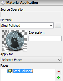
To select a material to apply, you can use field Material in the properties window. Material of the current model can be selected from the drop-down list. To open properties window use ![]() button.
button.
![]()
To call the operation parameters use option:
|
<P> |
Set entity parameters |
To cancel selection of all faces, use the option:
|
<K> |
Cancel selection of all faces |
||
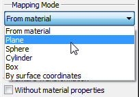
In the command's properties window, additional parameters of the texture mapping can be specified: The “Mapping mode” group allows us to select the material mapping mode and the scale of the texture along different axes. In the drop-down list of mapping modes the following options are available: 1.From material – all parameters are taken from the properties of the material. |
|
|||
2.Plane – mapping is carried out as if the texture is projected along the normal to the plane on which the texture is located, i.e., on the XY-plane of the manipulator.
3.Sphere — mapping is carried out as if the texture is located on a segment of the sphere. This option is convenient for mapping textures on spherical and close to spherical surfaces. Parameters of the sphere determine the scale of the texture of the material and are controlled by the manipulator.
4.Cylinder – similar to the sphere but the type of the surface is different.
5.Box – it is assumed that the textures are mapped on the faces of a parallelepiped and are projected from these faces. For this mapping mode, additional scale along the third coordinate is used. The scales thus define the dimensions of the «template surface».
6.By surface coordinates – this mapping is useful for curvilinear surfaces. For this mapping mode, the texture coordinates are associated with internal coordinates of the surface. It can be considered as a generalization of the texture mapping on a sphere or a cylinder. The texture is always displayed on the surface in a unique way, therefore, the manipulators are not used.
To control the mapping of a texture and its accurate positioning, the intuitively clear manipulators are used. The view of a manipulator depends on the selected mode of material mapping. All parts of the manipulator are functional. For each element of the manipulator there is the context menu with various fixings and commands.
More information about manipulators can be found in the chapter "3D Assemblies Creation".
The “Texture transformations” group allows us to specify for the texture the mapping parameters that are different from those specified in the properties of the material itself. The “Without properties of material” flag determines the source for the parameters of the mapping. By default it is disabled and the mapping parameters are taken from the properties of the material. When the flag is enabled, the user can specify new values of the parameters (“Direction S”, “Direction T” and so on.)
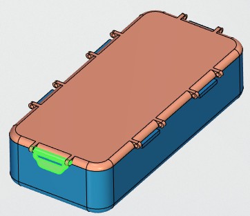
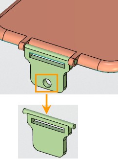
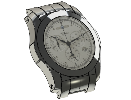
Example of Applying Image to a Face
An image of a wristwatch dial will be applied to the face of a watch body as an example of using “Apply Material” command.
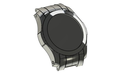
First, you need to create the coating material. Color texture of the material will be specified by image file. In this case coating material named “Clock-face” was created. The image file “Clock-face.jpg” used as the color texture. It is located in the folder: “T-FLEX Parametric CAD 14\Libraries\Examples\3D modeling\Apply material”
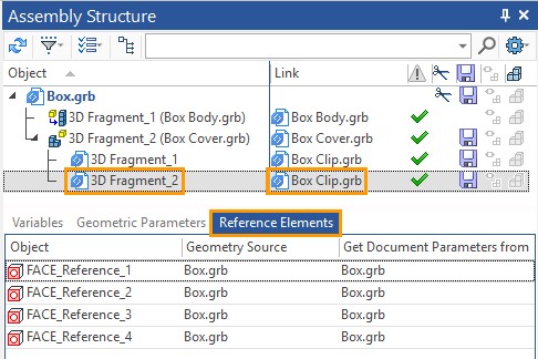
The example is located in library “Examples\3D modeling\Apply Material\Watch.grb”.
In order to apply the material "Clock-face" on the selected face of the watch base you should:
1.Open the file with watch body on which the material will be applied;
2.Add Clock-face material to the list of materials of the current model.
3.Activate command “3AM: Apply Material” ![]() ;
;
4.Select required watch face with the help of option Select face ![]() ;
;
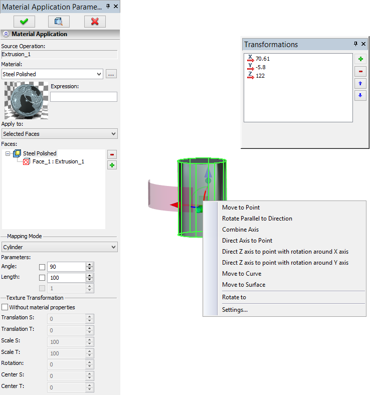
5.Select “Clock-face” from drop-down list in Material Application window
6.Select plane in mapping mode drop-down list.
7.Specify positioning of material on the face with the help of special manipulators in the 3D scene and the Texture Transformation group in properties window.
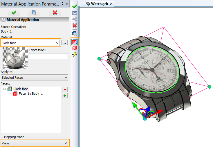
8.Press ![]() .to finish input.
.to finish input.
Usage of Drag’n’drop and “Copy/Paste” commands to apply materials
You can edit body, operation and face materials not only from the clipboard with the help of Copy and Paste commands, but also using drag’n’drop: moving the selected material and “dropping” it to a face or a body .
If there are several program instances running on the computer, you can apply materials from one instance to the model of the other instance using drag’n’drop. T-FLEX CAD can use materials from datasets of T-FLEX DOCs application running on the same computer including integration mode.
Copying into clipboard is performed using option “Copy” from the context menu. In “Materials” window materials from the list of the current model material and from the libraries list are copied using item “Copy” from context menu or by pressing <Ctrl>+<C>. The “Copy to Document” command (<Ctrl>+<D>) copies material from the library to the list of the current model material and to the clipboard simultaneously.
When you copy material to the clipboard, name of the material is available for pasting into any text editor.
The material from the clipboard will be applied to the selected objects: bodies and faces, when you use command “Paste”. If there are no objects selected, a dialog window appears. In this window, you can choose applying of the material to all bodies in the scene. If you refuse, the material will be placed in the list of the current model materials.
The system checks existence of coating materials applied to body faces when you use “Copy/Paste” commands or drag’n’drop to apply the material to the operation. If any coating material is already applied to one or several faces, the following dialog window appears:
If you press “Yes”, all previously applied coating materials will be deleted. If you press “No”, the material will be applied only to faces without applied material. Button “Cancel” cancel applying of the coating material.
The coating material can be applied to faces and bodies, even if all filters are disabled.The appropreate filters become active when you work with the coating materials. For convenience, you can disable one of them.
![]()
The basic material is always applied to the whole body.
When you use drag’n’drop T-FLEX CAD helps you to select object for material applying. For this purpose selected objects are highlighted with red and tooltips appear near the mouse cursor. In addition, the material preview window appears in the scene.
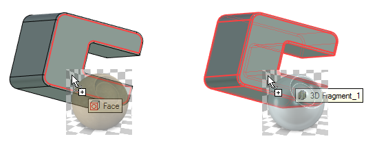
When you use drag’n’drop, system shows the last operation, which was applied to the body.