Use of 2D Projections


Use of 2D Projections |
|
Working with 2D Projections of Type “Precise (Image Lines)”
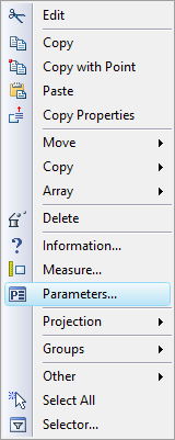
A 2D projection of type “Precise (Image Lines)” is a special element in the system. The drawing only displays the direct children of this element, that is, graphic lines and hatches. Together, these elements make the image of the projection. Most of the properties of each element are taken from the projection customization settings at the time of creation. These are, for instance, types of various projection lines, Color, Scale factor, priority, etc. however, if desired, each element properties can be modified separately. This can be done via the element parameters dialog box, conveniently accessible from the context menu. As usual, it appears in the right click ![]() over the element.
over the element.
Depending on which element was selected by right-clicking ![]() (whether the 2D projection itself or a child element), the context menu will have different contents.
(whether the 2D projection itself or a child element), the context menu will have different contents.
If an immediate child of the projection is selected (such as a graphic line or a hatch), then its own context menu will have some additional specific commands to work with the 2D projection. In this case, there is also a difference in the action of the standard “Delete” command . In this case, it does not actually delete, rather merely hides the selected element. This can serve to hide some “unnecessary” elements of the projection.
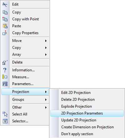
Projection editing is activated by the “Edit 2D Projection” command. To delete the whole projection, use the command “Delete 2D Projection”.
Next in the list is the command “2D Projection Parameters” that is used for calling the projection parameters dialog box. This dialog allows defining some general properties of the projection elements (line types, Color, Type and hatch display), as well as all the rest of the projection settings. Details on handling this dialog box are presented in the respective section of this chapter.
The projection is not regenerated as the 3D model updates. To have the model changes reflect on the drawing (projection), either start the full model regeneration or update the projection manually by the command “Update 2D Projection”. A special parameter on the tab “General” of the projection parameters dialog box controls the ways of updating the projection (see description above). The command “Update locally” provides greater time saving when handling complex models and drawings. Unlike the previous one, this command does not start regeneration of the children elements. This is convenient for working with projections that take long time for regeneration and are subject to projective relations.
|
|
The context menu upon selecting a projection line |
The context menu upon selecting a 2D projection |
The context menu of the 2D projection proper has several additional useful commands.
There is the command “Restore deleted elements” that serves to restore the "deleted" elements (lines or hatches hidden by the “Delete” command).
If necessary, you can break the relation between the projection image and the 3D model, and turn the 2D projection into a collection of nonparametric unconstrained graphic lines and hatches. You use the “Explode Projection” command for this purpose.
If the 2D projection is constructed based on a model from an external file, then you have the command “Open” which opens the document related with the projection.
The command “Create Dimension on Projection” serves to carry the 3D annotation elements over to the 2D projection (see the paragraph "Creating annotation elements").
When projecting two or more bodies penetrating each other, there could be inaccuracies in defining the lines of bodies intersection and the lines visibility. Therefore, it is recommended to join such bodies in one by using the Boolean operation whenever possible or use the parameter “Allow intersecting bodies” before projecting (see the description of the parameters dialog box). Turning on this option increases the time of the projection regeneration.
Some 3D elements can be created based on a 2D projection, such as workplanes and 3D sections. The respective options are provided in the automenu sets of the commands creating the respective elements.
2D projections can be later used as references for construction lines, dimensions, detailing elements, etc. When creating construction lines, object snapping is engaged to the projection elements, distinguishing circular arcs, ellipses, splines, line segments, end points (nodes) of lines, arc centers, etc.
Some graphic lines created based on a 2D projection have additional parameters. For example, there are graphic lines of a special type “spline curve”, which may sometimes be generated when projecting. You can additionally specify the number of spline points for a graphic line of this type, if you find the mapping accuracy not satisfactory (it is 40 points by default).
![]()
![]()
Working with 2D Projections of Types “Vector Picture”, “Shading”, “Rendering”, “Wireframe”
On the drawing 2D projections of types “Vector Picture”, “Shading”, “Rendering”, “Wireframe” represent themselves (in contrast to 2D projections of the type “Graphic Lines”) inseparable objects. Parameters of separate elements of such projections cannot be modified.
In other respects, working with 2D projections of these types is similar to working with the projections of the type “Precise (Image Lines)”. The context menu of similar 2D projections duplicates the context menu of the 2D projection of type “Precise (Image Lines)”.
When creating 3D annotations on the 2D projections of the types “Vector Picture”, “Shading”, “Rendering”, “Wireframe”, the annotation elements being created are attached directly to the elements of the 3D model.
Creating Annotation Elements
To accomplish a drawing created based on a 2D projection, you can use standard 2D commands – “D: Create Dimension”, “IN: Create Leader Note”, “RO: Create Roughness Symbol”. Dimensions, leader notes and roughness symbols can be created on the projection lines in the same way as on a common drawing.
If the 3D model was modified significantly, the composition of projection lines and some element IDs might change to some extent upon the 2D projection recalculation. In such a case, some of the annotation elements based on the lines produced by the 2D projections may lose their relation with their source elements . The system will notify the user about it with a message in the diagnostics.
A 3D model may include 3D annotation elements - dimensions, leader notes and roughness symbols, applied directly in the 3D window on the model faces. Those serve to make the 3D model appearance more intuitive and simplify modifying its geometrical parameters. Besides that, the information stored in 3D annotation elements (such as tolerance parameters in a dimension, its additional text lines, roughness symbol parameters, etc.) can be carried over to the counterpart 2D annotation elements in the projections of the given model. For details on creating 3D annotation elements refer to the chapter “3D Annotations”.
If there are 3D dimensions or roughness symbols on the current 3D model, then, when creating 2D dimensions and roughness symbols on the respective projection lines, the system can automatically find the correspondence between the element being created and its counterpart element in 3D. If such a correspondence is found, then all parameters from the 3D dimension or roughness symbol (the nominal, tolerance, text lines, etc.) will be carried over to the 2D element being created. If any of such parameters are to be changed in the 2D element, then you should modify its counterpart element in 3D.
The data transfer from 3D dimensions onto a 2D projection can also be accomplished by a direct “mapping” of the dimensions from the 3D space onto the 2D projection. This is done using the “Create Dimension on Projection” command available in the context menu when called over a 2D projection.
Upon calling the command, the system determines, which of the 3D dimensions existing in the model can be mapped on the selected view (projection). In addition to 3D dimensions, the dimensions from the workplane, which are displayed in 3D scene, can be offered for being drawn on the projection under condition that the workplane is parallel to the projection plane.
The system-selected dimensions are drawn on the projection in red. The user needs to specify, which of the system-supplied dimensions shall be created on the given 2D projection.
You select the dimensions using the following options of the command's automenu:
|
<M> |
Select Detailing Elements |
|
<M> |
Cancel Selection |
|
<*> |
Select All Elements/Cancel Selection of All Elements |
|
<End> |
Finish Element Selection |
When the ![]() option is active, the dimensions are selected that shall be created on the given projection. To select a dimension, simply point the cursor to the desired dimension in the 2D window and click
option is active, the dimensions are selected that shall be created on the given projection. To select a dimension, simply point the cursor to the desired dimension in the 2D window and click ![]() . The selected dimension color will change to blue. In this way, you can select any number of dimensions in a series.
. The selected dimension color will change to blue. In this way, you can select any number of dimensions in a series.
Activating the option ![]() starts the mode of canceling the selection of dimensions. In this mode, picking a dimension by
starts the mode of canceling the selection of dimensions. In this mode, picking a dimension by ![]() cancels its selection. As a result, the dimension color turns back to red.
cancels its selection. As a result, the dimension color turns back to red.
The effect of the option ![]() depends on which of the above-mentioned options is active. If the
depends on which of the above-mentioned options is active. If the ![]() option is active, then using this one will cause all system-provided dimensions to become selected, whereas with the
option is active, then using this one will cause all system-provided dimensions to become selected, whereas with the ![]() option active – it will do the opposite, canceling all dimension selection.
option active – it will do the opposite, canceling all dimension selection.
You can confirm the creation of the selected dimensions on the projection using the option ![]() .
.
Modes of Displaying Dimensions on 2D Projections
Dimensions created on 2D projection lines can be displayed in two ways. The first method is the standard display of dimensions (in the plane perpendicular to the viewing direction). The second method is “spatial” display of annotation elements. The latter is usually used in nonstandard and “spatial” views (such as in the axonometric). In this mode, the dimensions created based on projection lines will be drawn in the plane of the selected elements. For example, if a dimension is applied to an elliptical projection image of a circular edge, then the dimension will be maintained in the plane of the circular edge. This capability helps creating dimensions with actual values on axonometric views.
This capability is controlled by the “Save information for 3D dimensions” option on the “General” tab in the 2D projection properties (see the section “2D Projection Parameters”). You need to update the projection after enabling this option.
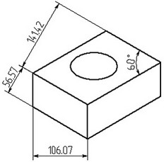
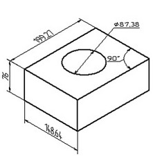
Dimensions on a 2D projection in the regular mode Dimensions on a 2D projection in the “3D” mode
The “spatial” method of displaying dimensions on a drawing can be used with all types of dimensions except construction ones.
Using Dimensions on a Projection to Manage the 3D Model
2D dimensions created on projection lines can sometimes be used to modify the 3D model. This is possible in the cases when the system managed to find a correspondence between the projection lines on which the dimension was created, and the control elements of the 3D model. Such elements may include faces of the 3D model dependent on the geometrical parameters of operations or on 2D constructions that provide the base for the 3D model operations. The system automatically tries to find such correspondence when dimensions are constructed on the 2D projection. If the system succeeds finding such correspondence, then the changes to the dimension values will affect the 3D model and its projections. You change the dimension value using the command “PE: Set Dimension Values”, described in detail in the chapter “Modifying the drawing using dimensions”.