T-FLEX CAD 17 - new tools for complex high-tech product high quality design, increased performance, improved interface and hundreds of user proposed innovations
What's New in T-FLEX CAD 17 and Add-on Modules
T-FLEX CAD 17 offers a large number of new functionality and improvements, many of which are implemented according to users' requests, including: significant increase in performance when working with large assemblies, teamwork using T-FLEX DOCs, new tools for 3D design, new operations for surface modeling and working with 3D curves, improved user interface, and much more.
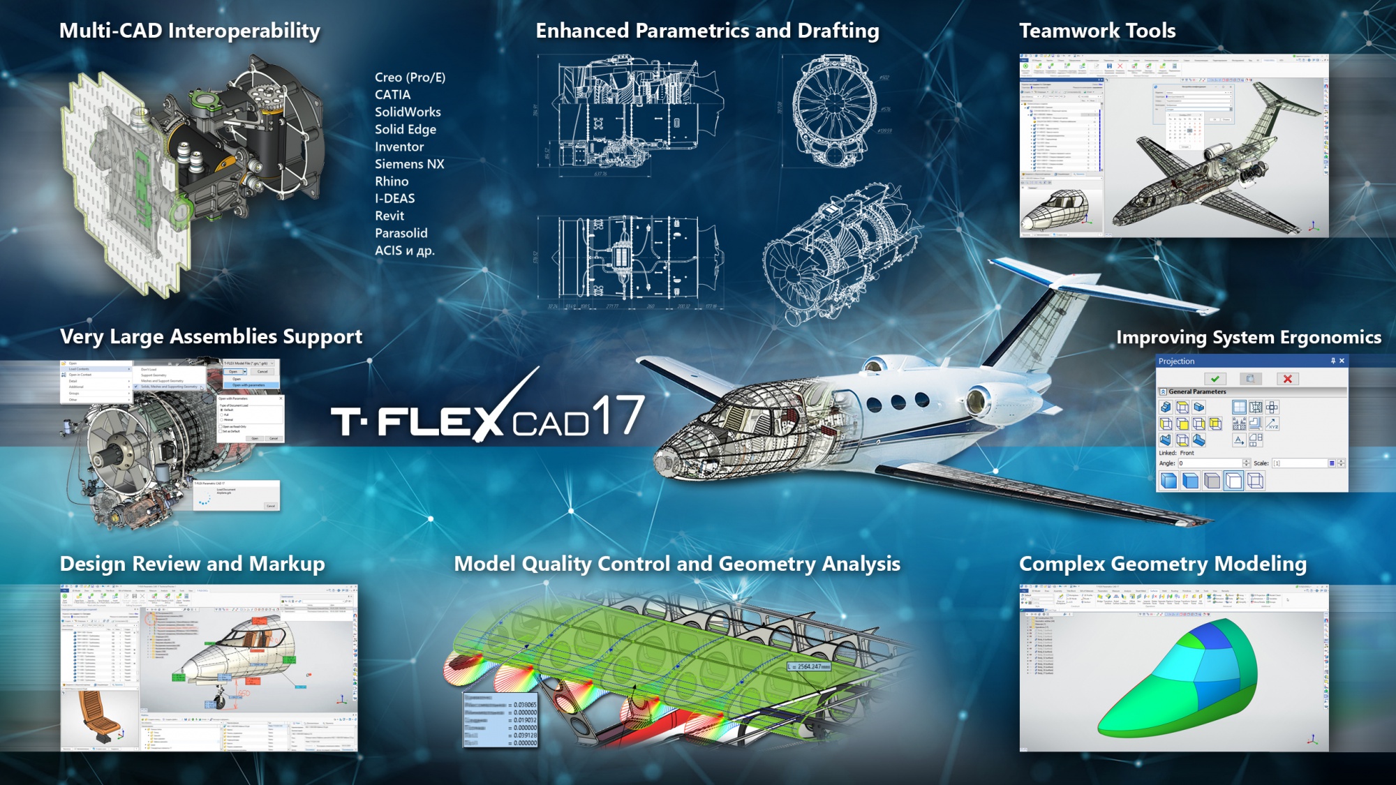
Large Assemblies
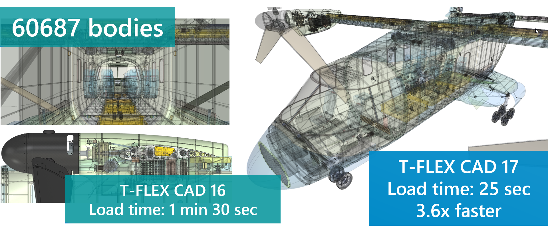
T-FLEX CAD 17 received new tools for working with large assemblies.
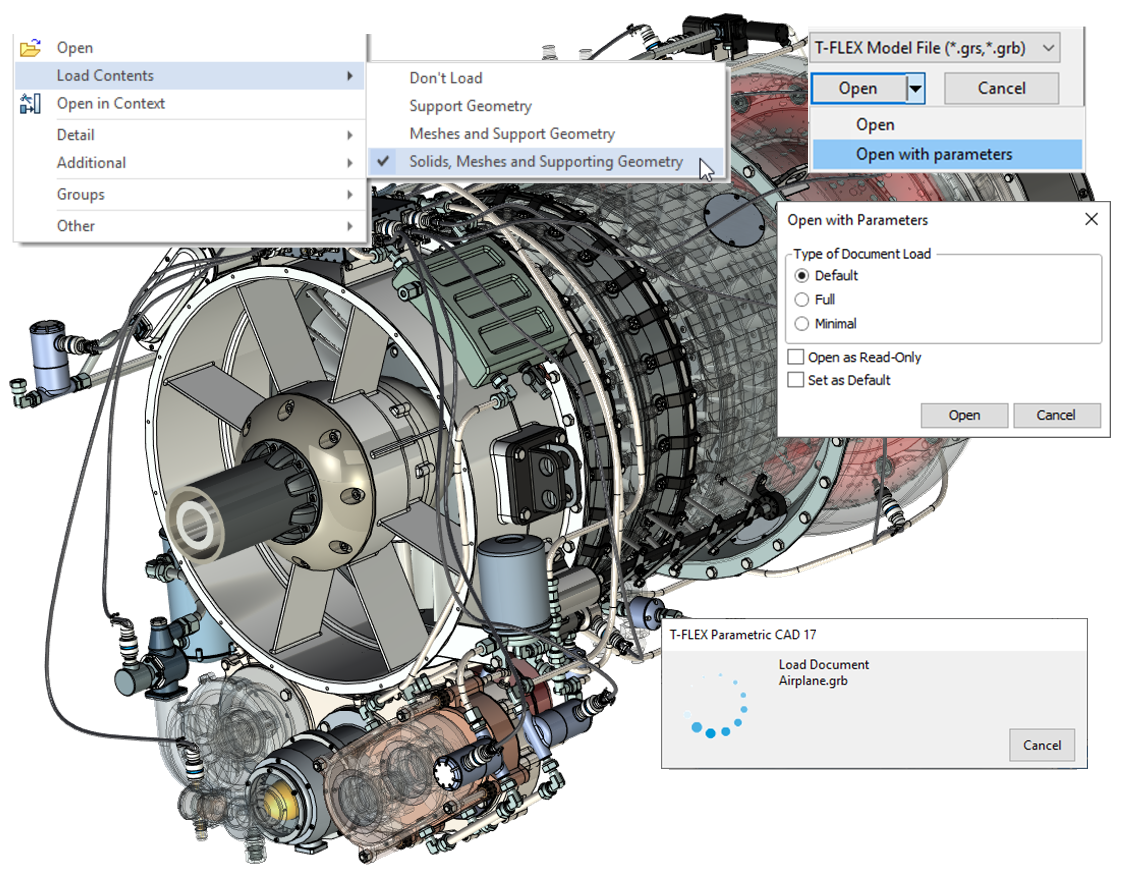
Opening of files is now up to 10 times faster, memory consumption reduced, large assemblies mode enhanced, new assembly management commands added, interruption possibility for file loading process supported, new open file settings introduced, parallel multithreaded loading of 3D models visualization meshes added, data import from other CAD systems accelerated, etc.
Teamwork under T-FLEX DOCs 17 Control
New configuration mechanism for teamwork with T-FLEX DOCs 17 has been developed, functionality for working with the product structure has been improved.
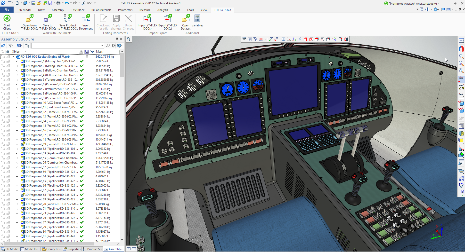 Teamwork in T-FLEX CAD 17 under T-FLEX DOCs 17 Control
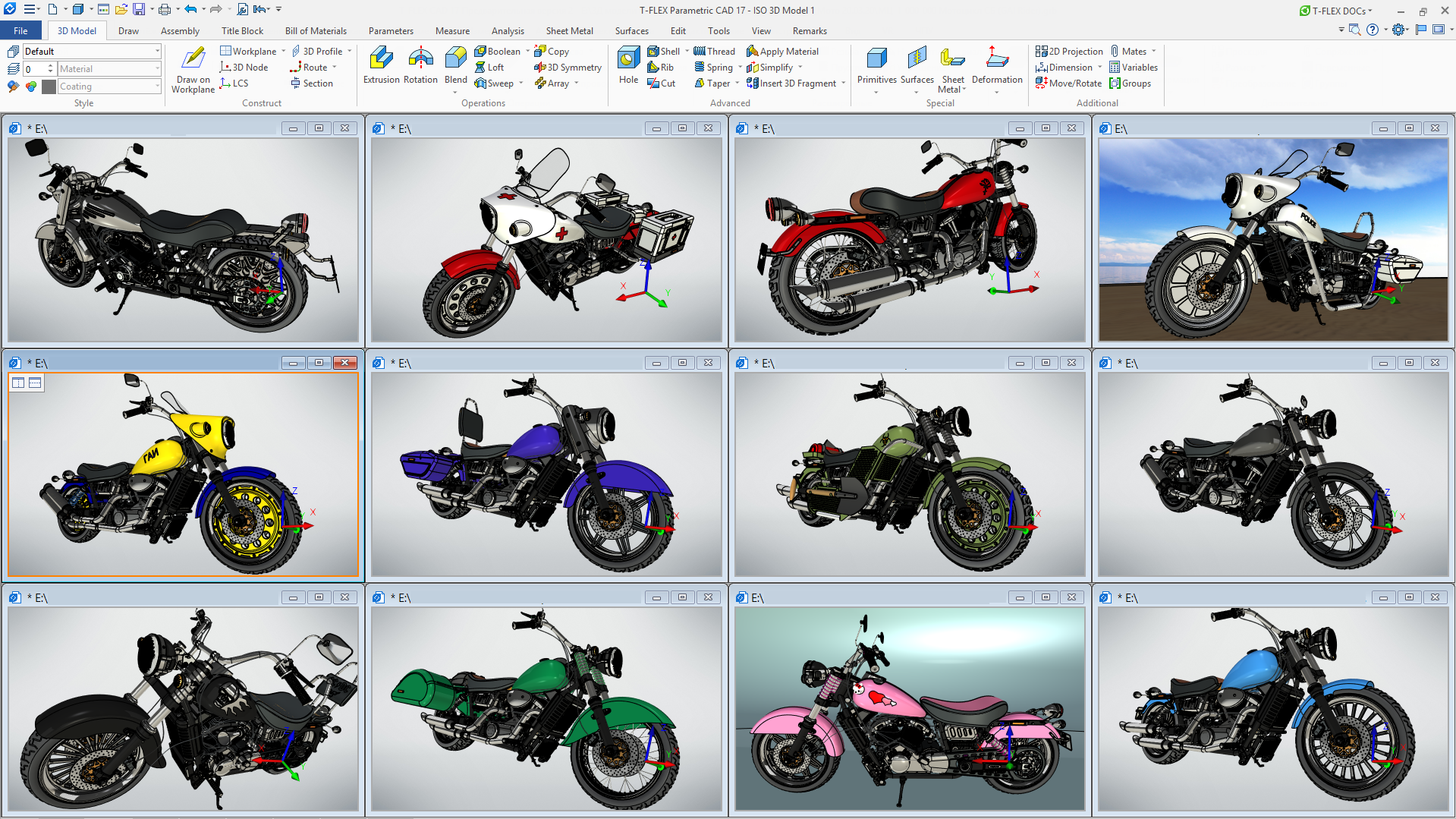 Various Assembly Configurations in T-FLEX CAD 17
New Annotation Functionality - Review and Annotate 3D Models and Drawings
The existing functionality of annotations has been transformed into the new annotation tools.
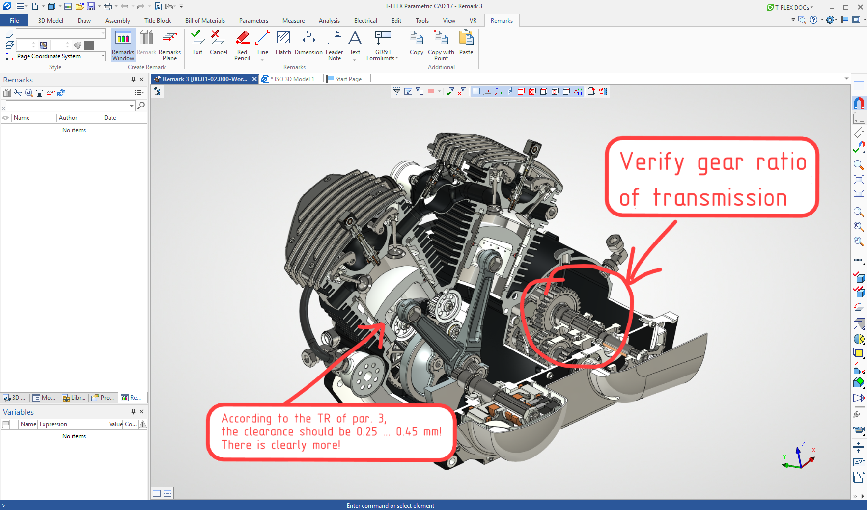
The new mechanism works both separately in T-FLEX CAD and T-FLEX Viewer, and under the control of the new T-FLEX DOCs 17. New window and ribbon for managing and creating notes were added. It is now possible to create notes both on drawings and on 3D models, new "Red Pencil" function has appeared for quick remarks - drawing "by hand" with support for input from tablets, notes are stored in separate files or in a new folder. Notes when working under control of T-FLEX DOCs 17, in team mode within T-FLEX DOCs are saved as T-FLEX DOCs objects without using files.
Surface Modeling, Wire Geometry
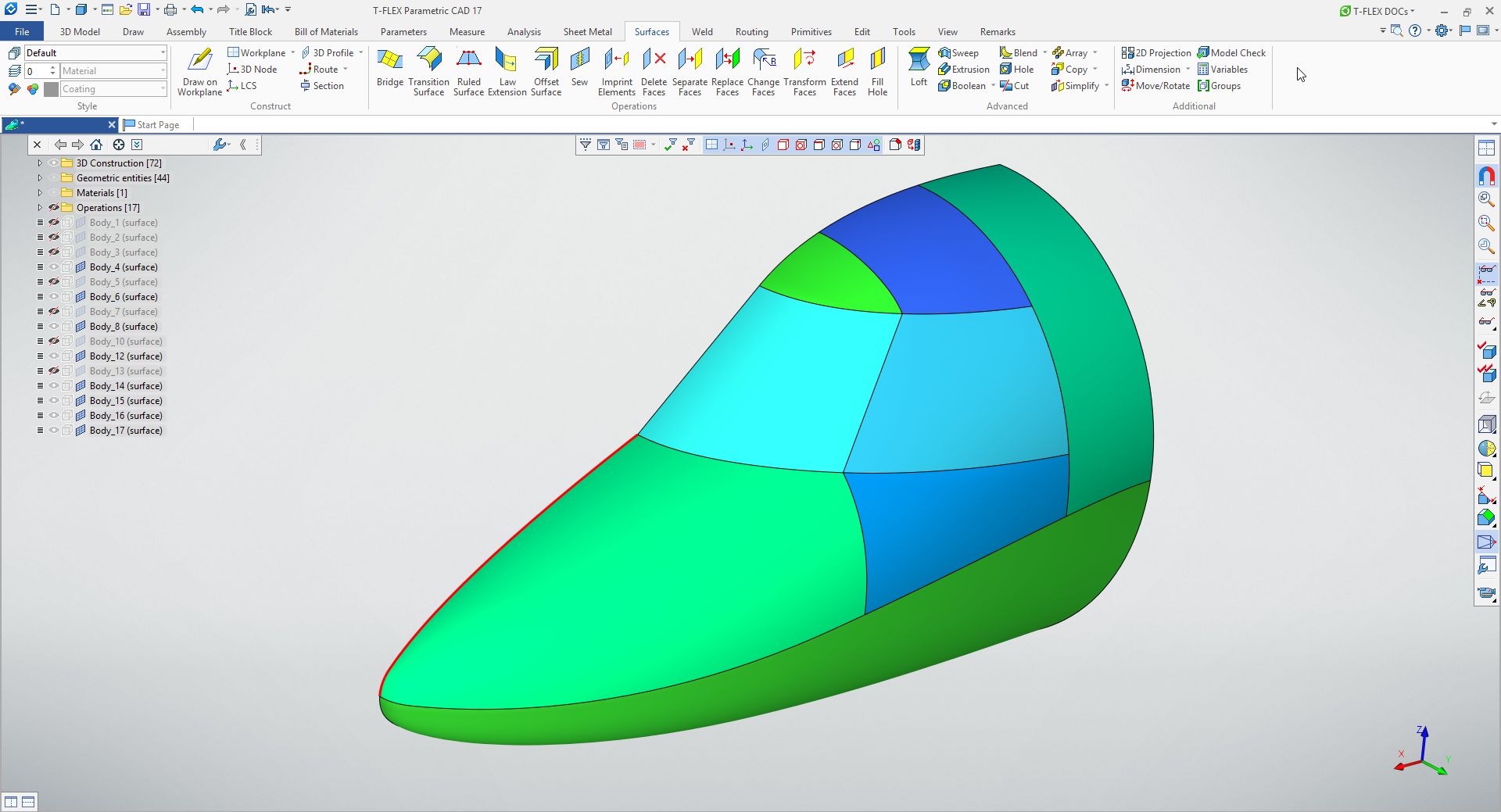
Significant improvements have been made to the functionality of surface and wireframe modeling - four new surface modeling operations have been developed: transition surface, ruled surface, law continuation, offset surface. Operations for working with faces have been modified - stitching, filling in an area, etc.
New tools were also developed for working with wire geometry: transition curve, isoparametric curve, conical curve, 3D curve editing operations (lengthening / shortening), spiral path, connecting curve, etc. These new tools are aiming various design areas including aerospace, shipbuilding, complex geometric consumer goods.
Geometry Measurement and Analysis Tools
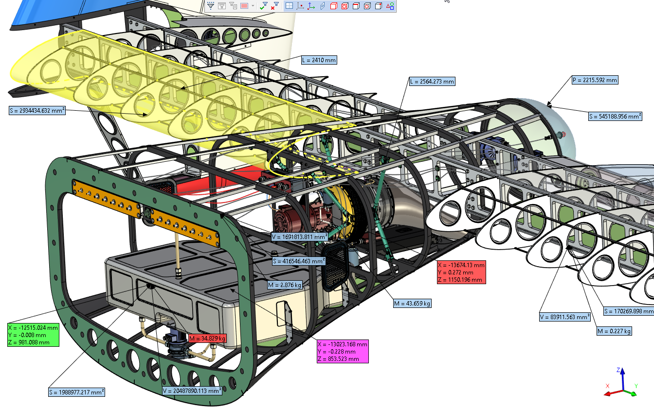
New tools have been created for more accurate analysis of the modeling results, obtained, including through new surface and curve modeling operations. In addition, the usability of the existing functionality of the Measure command was improved.
3D Modeling Tools for General Engineering
Operations Extrusion, Rotation, Blend, Boolean, Shell, Sweep, Primitive, Cut, Arrays have been seriously improved, new features added, dialog boxes now have more convenient interface and customization options. New operations were added - Offset body, Array by Pattern, and new type of array - array of 3D fragments. The comfort of work was significantly increased, including reduction of the number of clicks when designing.
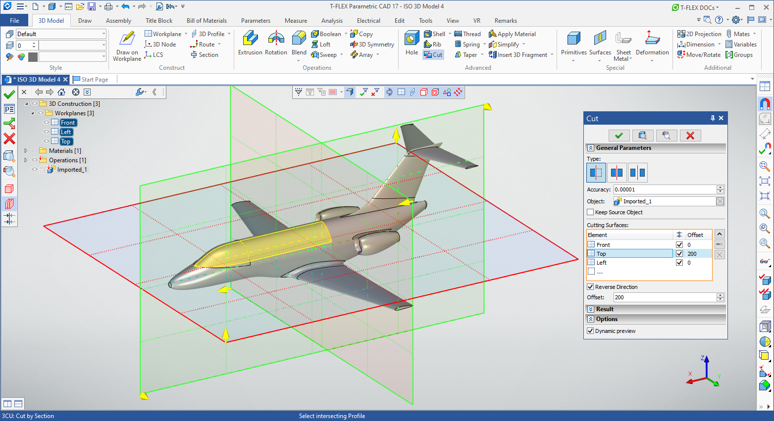
It is also worth noting the updated functionality for working with 3D sections, trim plane, and Cutting operation. These tools have been unified, have now the same control manipulators, and have become more convenient and faster to work.
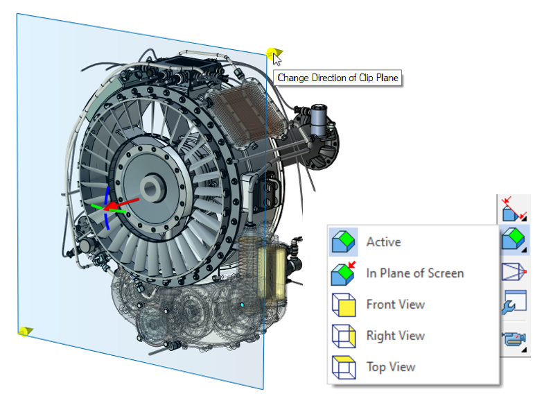
3D Model Tree in Creation Order and Other Updated System Windows
The new version has the ability to display the 3D model tree in the order of creation. In addition, the material windows, the document menu have been seriously updated, windows for managing layers, configurations, and purging have been added. Search bar and other common tools have been added to all windows.
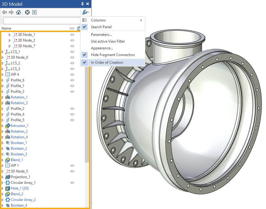
3D Model Tree in Order of Creation
The new version adds mechanism for checking the modeling result according to corporate rules, checking the quality of the model, new features in the variable editor, updated mechanism for selecting 2D and 3D objects, new settings in the interface - changing the model rotation button in the 3D scene, presentation mode, new start page, and much more.
The import module now has the ability to directly read and import the CATIA v.5 (R2020) format, as well as support for the new versions of PTC Creo, Siemens NX, SolidWorks, Solid Edge, Autodesk Inventor and other formats.
2D Design and Drawings Detailing
In the new version, the mechanism for creating 2D projections has been improved. Users will get a new, more user-friendly interface with a choice of additional isometric views and stages of the disassembly scenario.
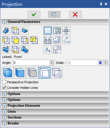
Updated Dialog of Parameters for Creating 2D Projections
In 2D design and drawings detailing, new functionality has been added for technical notes, for working with the drawing zones. New features for spline curves were added. New type of 2D arrays introduced - according to a table. New mechanism allows creating hyperlinks in the drawings.
Libraries of Standard Parts
When developing the new version, much attention was paid to the libraries of standard parts: many standard elements according to ISO and DIN were revised and updated, new standard elements were added.
T-FLEX Electrical 17
In the new version of T-FLEX Electrical 17 module, much attention was paid to schematic design tools. For designers, these changes will translate into greater visibility into the data-driven design, as well as greater automation of their actions.
For example, for any of the elements in the context of the scheme, you can run the command to view its composition and parameters, which is especially important for exploded elements. The elements themselves received a separate command to manage the grouping of the exploded parts and track their current locations.
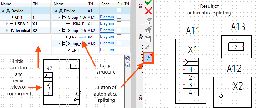
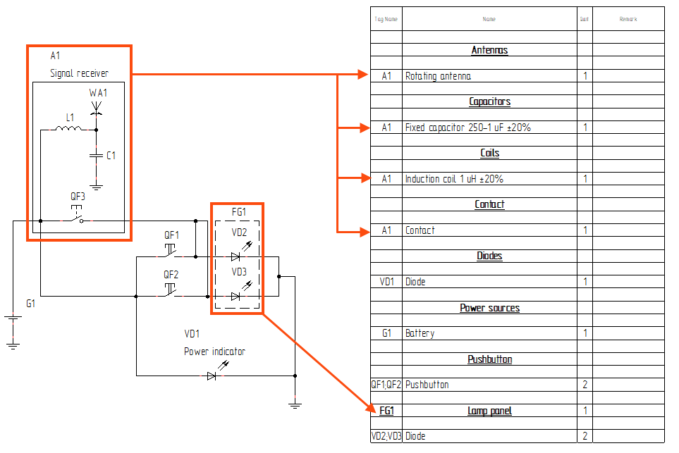
The composite elements of schemes received several additional ways of their contextual creation, as well as the ability to save as a library element. Now they can be additionally combined into groups directly in the scheme at the discretion of the user, which will allow you to flexibly configure the options for displaying elements in reports, as well as information common to them in the scheme:
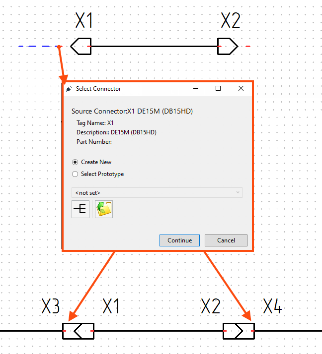
Elements such as Connectors have acquired the ability to contextually form a connection (plug-socket) and an automated search for a suitable mate. The system will offer to create the response part automatically, you just need to connect the wire (communication line) from the mounting side of the current connector:
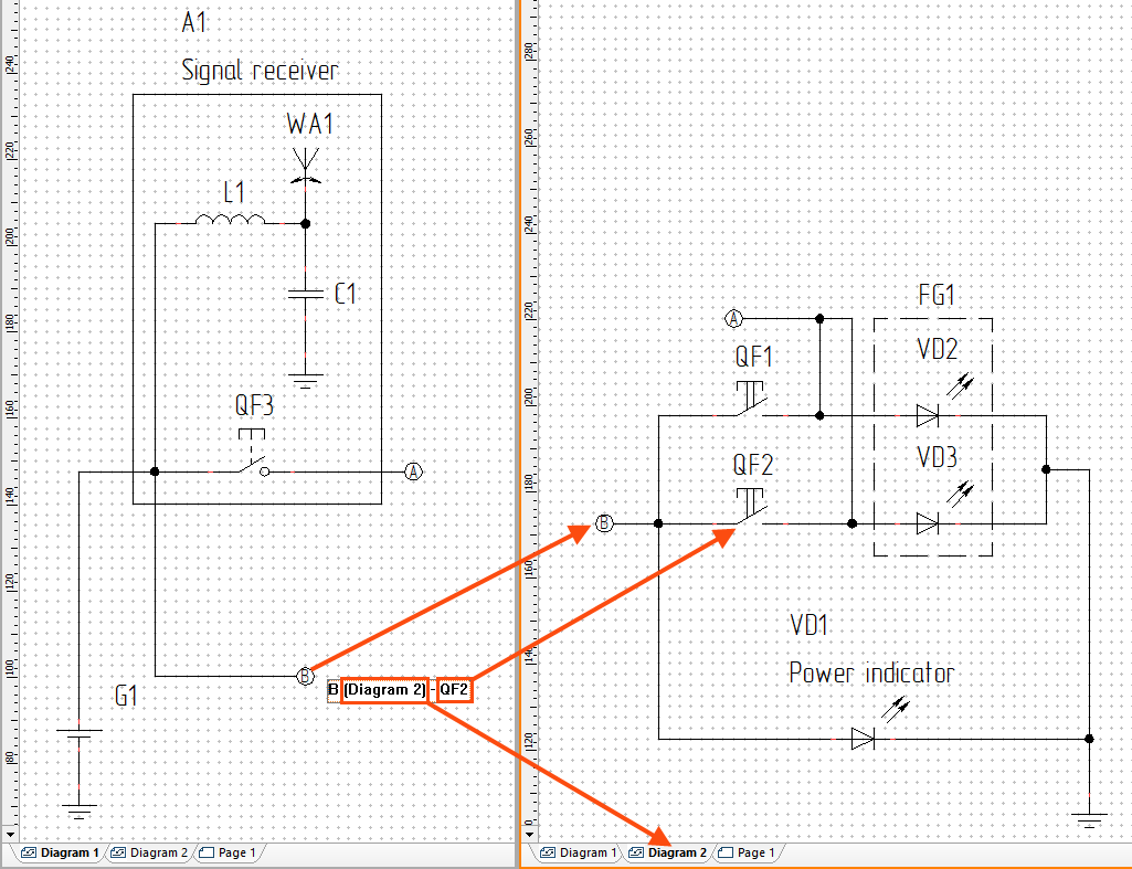
For the convenience of scheme engineers in multi-page mode, functions of hyperlinks to breaks in communication lines have been added. Now it has become even easier to "travel" according to the scheme:
Several important improvements were made to the tools for working with 3D geometry of cable products. In the new version of the module, the mechanisms for working with the topology and composition of the harness have been improved - individual parts of the harness can be fixed from automatic system adjustments, and the harnesses themselves can now be used as independent objects of the 3D scene and do not necessarily need to be linked to the scheme.
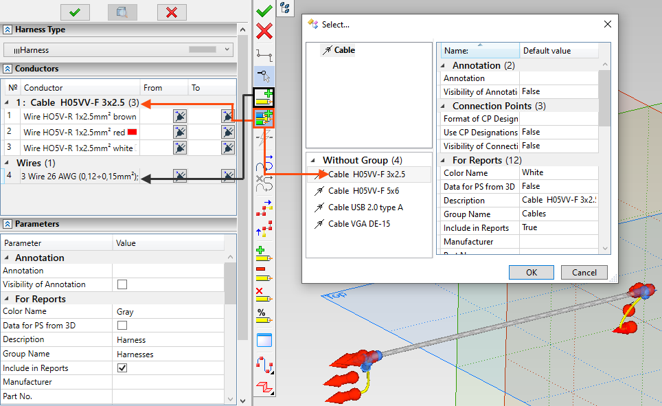
Mechanisms for analyzing scheme and geometry data for cable products have been added to the system. They include a number of basic checks for possible "mechanical" errors of designer.
In other areas of the module's functionality, albeit smaller-scale, but no less significant improvements were also carried out: several new types of tabular reports were added, the ribbon of the module's main tools was redesigned, the flexibility in formatting the schema data was increased, including separate control of caption fonts on diagrams, their orientation output of additional information, and much more.
T-FLEX Analysis 17
The Analysis module is developing simultaneously in various directions: new types of elements, new calculation methods, modeling new physical effects, module interface. As a result, Analysis has become more convenient, faster and more stable, and the list of studies to be solved has become even wider.
New algorithms for solving problems have been added - inertial balancing, for a linear tetrahedron the Alpha method option has been added, the use of which leads to more accurate calculation results for both displacements and stresses. An updated calculation of stresses has been implemented. Calculation of shell structures has been accelerated. It is now possible to calculate heat transfer by radiation between the surfaces of bodies. Changes have also been made to user interface. New functionality has been added to reports based on the product structure.
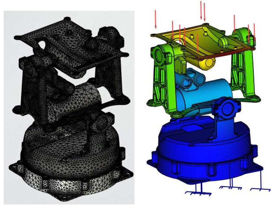
Using the Alpha Method Option in Calculation
T-FLEX Dynamics 17
The resulting calculations in Dynamics are now more convenient to analyze and, most importantly, any calculated state of the model can be transferred to T-FLEX CAD and T-FLEX Analysis applications. In addition, the work with mates has been improved, the accuracy of calculations and the stability of calculations have been increased.
Now it is possible to create a 3D path along the trajectory of the sensors movement, each position of the dynamics of the movement of design objects can be unloaded into a separate T-FLEX CAD file. It is now possible to automatically stop the calculation when the sensor indicators reach the user-defined limits. Graphs can be now generated as a cyclograms. New command "Move with a constant speed" was added. For bodies whose rotation depends on each other, a new loading mechanism has appeared. In addition, a choice of units of measurement is available in the dialog, and the sensors can be hidden.
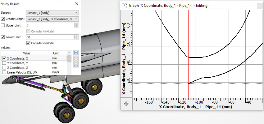
Calculation to a Given Position
T-FLEX CAM 17
A significant number of changes have been added to T-FLEX CAM 17 module, which include functionality for working with toolpath arrays, the ability to change the colors of toolpath segments, new possibilities in 3D milling, engraving. The processing manager window has been redesigned, the ability to form installations with different positions is now supported, configurations and set of rigs has been added, and much more.
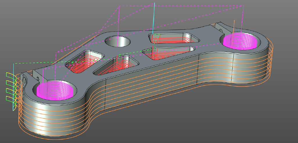
Color Modification of Toolpath Segments
T-FLEX VR 17
T-FLEX VR module continues to evolve. The dialogue for working with a model in VR space has become more logical and convenient. There are new commands for measuring the model.
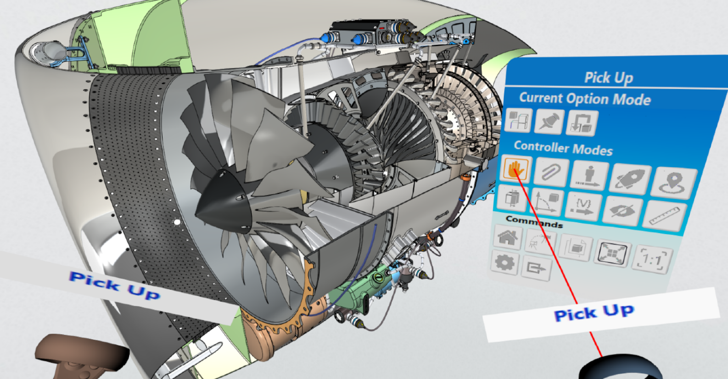
Both modes and commands allow you to modify the virtual space or set display settings.
T-FLEX Viewer 17
T-FLEX Viewer has become an even more convenient tool for quick viewing and control of projects in teamwork. Is now possible to use the new mechanism of remarks, including work in the Remarks window. You can measure models using the command to measure and calculate mass-inertial characteristics. For detailed viewing of models, commands for applying 3D sections and trim planes are available. In addition, visual display parameters are available, as well as options for searching for models in 3D scene and in the 3D Model and Assembly Structure windows. An ability to edit 3D models using manipulators and external variables was added.
T-FLEX Viewer supports playback of assembly / disassembly scenarios, which makes it possible to use 3D models as instructions for an assembler in production.
Work in T-FLEX Viewer now begins with a welcome page, where, like in T-FLEX CAD 17, you can define important files, access the resource center and training materials.
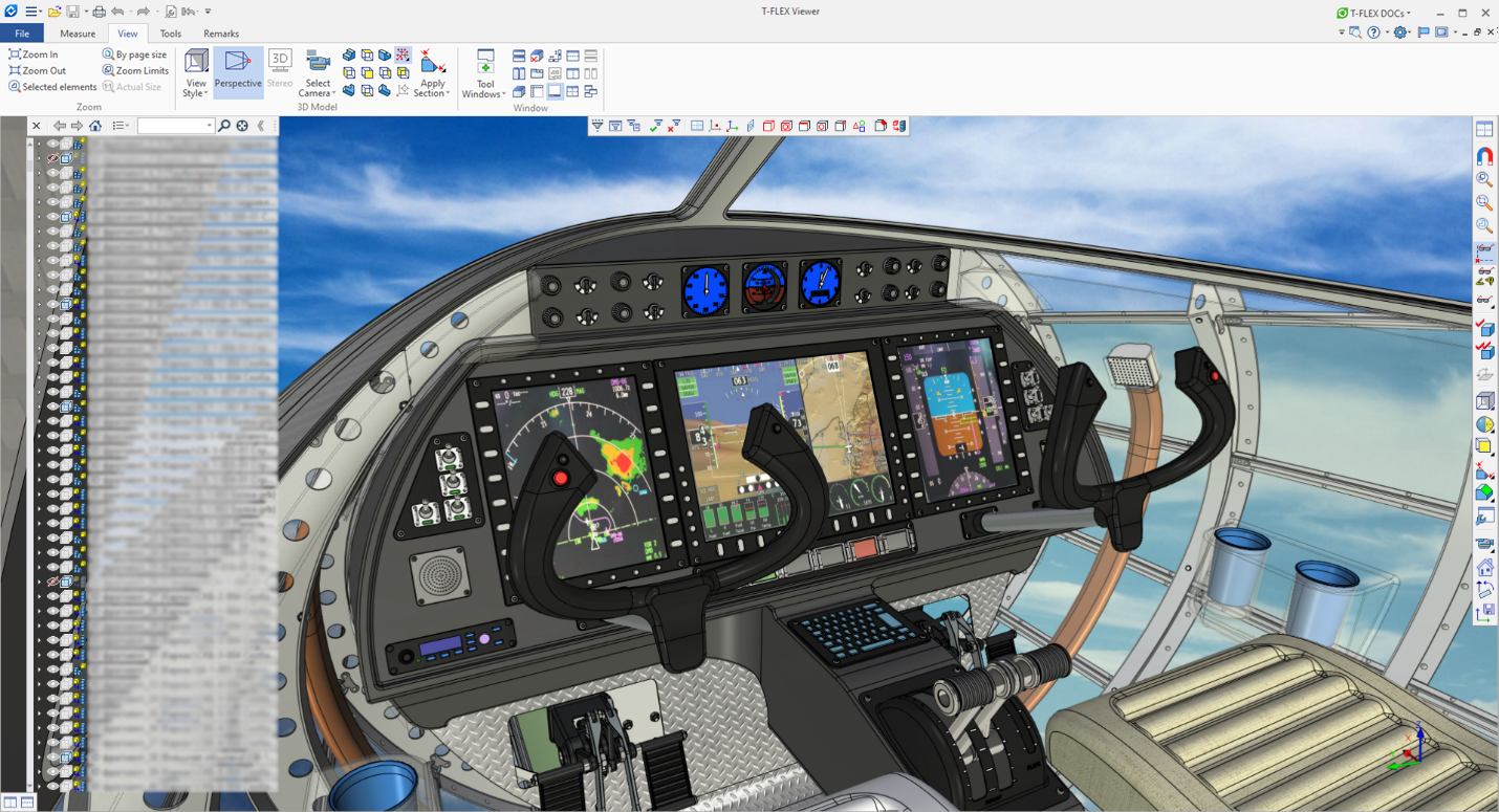
T-FLEX CAD 17 and add-on applications are part of a single integrated T-FLEX PLM software package from Top Systems and provide convenient teamwork together with the new version of T-FLEX DOCs 17 when designing products of varying complexity.
Trial versions are available for all T-FLEX products.