Design automation in shipbuilding production using T-FLEX CAD by experience of the Vyborg Shipyard
Author: Ivan Cheranev, lead designer of the Engineering process preparation department
We live in interesting time — a time of active technological progress, which is similar to a graph of geometric progression, accelerating with each step on the time scale. The graph of general technological progress consists of separate development curves of specific societies, enterprises, and people. And these curves are literally curves, as they oscillate in waves relative to the general, averaged trajectory of technology development, sometimes overtaking, sometimes falling behind. And the same waves of progress and technology come into the particular walls of particular industries and into the heads of people working there. Development of technologies in the field of production saves resources, and one of them is time, in a unit of which it is imperative to perform more and more work. A human is not capable to work at such rate. Automation salvages people in the form of a mechanism in a machine-shop and in the form of CAD in technical departments.
The Vyborg Shipyard (VS), as a modern enterprise, does not stay aside from technological progress. Its (progress) waves inevitably sweep through the offices of local departments of design and engineering process preparation. Among the waves, two of them are the largest. The first wave turned drawing boards into pieces of furniture and put computer mice in the hands of specialists instead of graphite pencils — that was the arrival of 2D CAD systems. The impulse of this wave greatly changed the work of a human, but it was not enough to change the design concept itself – it remained in the electronic drawing plane. But the second wave brought the third coordinate into the design process and extended a flat drawing to three-dimensional space, implementing 3D modelling technologies into the work.
The work of a tooling designer in the shipbuilding industry has its own specifics. Basically, of course, this is design of various equipment: from bench tool to technological equipment and large metal structures, including work with complex geometry of a ship's hull. This causes a requirement of wide versatility to a CAD used, as a result of this requirement the use of specialized shipbuilding software systems was deemed inappropriate, and the "multipurpose" mechanical-engineering T-FLEX CAD was chosen for "armament" of the Engineering process preparation department (EPPD).
The introduction of 3D technology at the enterprise was somewhat late (in the opinion of the author of these lines), and therefore there was a need to master it rapidly by employees. At the same time, it is important to achieve maximum efficiency in working with the system. And if efficiency is expressed as reduction in labor costs (and time as the main resource), then it becomes obvious that it is unacceptable to use this technology simply as a three-dimensional drawing board. It is necessary to minimize amount of common actions performed by a user by equipping him with a set of special tools for solving common tasks (which are the majority in total) and leaving him a "leading" role in modelling process. These tools, created in the environment of the CAD system itself, should shift the bulk of a common routine work to the system (constructions, calculations, etc.). An ultimate goal (ideal result) of introducing T-FLEX CAD into the work of the department may be implementation of the principle "Push the button —get the result" (maximum automation of design process). This goal is impossible, but quite real tasks can be solved on the way to it. At present, these tasks are being solved at the VS in several areas of work:
- working with models of a ship's hull received from a designer (review, taking measurements, applying sections, calculating masses and centers of gravity);
- modelling of ship’s hull assembly slipways based on existing designs of slipway tooling;
- modelling and design of various equipment and parts;
- design of rack and pattern assembly jigs based on a 3D model of a section;
- modelling of scaffolding based on a 3D model of a ship’s hull;
- building flat patterns, templates and other needs of lofting;
- stress analysis of tooling by the finite element method (a promising task).
These areas are developing in different ways (and with different success). The first way of design process automation is to create libraries of ready-made standard models, which, to a certain extent, reduce the work of a designer to assembly of a "construction set model". User libraries in T-FLEX CAD can include various models - both parts and assemblies, and varied parametric capabilities of the system and the use of an integrated tabular database allow you to get a large number of configuration options in one model. Thanks to this, as well as to quick access to these models through a special system window, application of such user libraries significantly speeds up modelling process. This method was used in design of slipways, scaffolding, metal structures.
A library of slipway equipment was the first of implemented ones. At the moment, it includes 30 models of varying complexity: from simple ones consisting of one or more bodies and having no variable parameters, to assemblies with more than a dozen variable parameters that control not only sizes, but also configuration (composition of models). Most of the models in this library are simple models, without variables, or with one or two variable parameters. These are various models of slipway supports and parts included in assemblies — plates, brackets, etc. They generally do not have special dialogs (windows) for setting parameters.
The most interesting elements (in the opinion of the author) of this library may be three most complex models: a model of a slipway unit on the basis of a slipway beam, a model of a keel-block and a model of a timber pad.
The model of a slipway unit is an assembly that includes a slipway beam with slipway trolleys and a set of supports (internal and external). All models, except for the slipway trolley, have been worked out in detail. A special dialog has been created to set parameters of this assembly.
The dialog is divided into three logical parts. The first part specifies parameters of the slipway beam itself (this is the main fragment of the assembly and it is always included in it, while all other fragments can be excluded on request): a constructional type (there are three in total), position height and presence of a timber. These variables (especially the height) are key to calculations that are performed in assembly variables (see below). The second part specifies parameters of the slipway trolley, which supports the slipway beam, specifically, its location in the assembly relative to the beam. In addition, a "location of the slipway" parameter affects a range of possible heights of the beam position (this is related to design features of a rail track). The third part controls composition of the assembly (excluding fragments and changing the beam supports). This dialog allows you to fully configure the model of the slipway beam at once when inserting it as a fragment into a slipway assembly.
Some configuration options of the slipway beam assembly are shown in Figure 1. In addition to the parameters set by a user, the assembly also automatically calculates number of underplates and height of a wedge support (it can be adjusted within 40 mm) and defines a need to replace the plates with a 100 mm high spacer (when specified height of the beam is large). All calculations in the assembly are carried out using standard functions of working with variables without using special plug-ins. At the moment, configuration options of this assembly cover almost all conditions in which this slipway unit can be used as a part of a ship’s hull slipway or a slipway for equipment mounting.
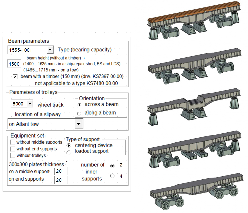
Figure 1 - Parameters dialog and configuration options for the slipway beam model
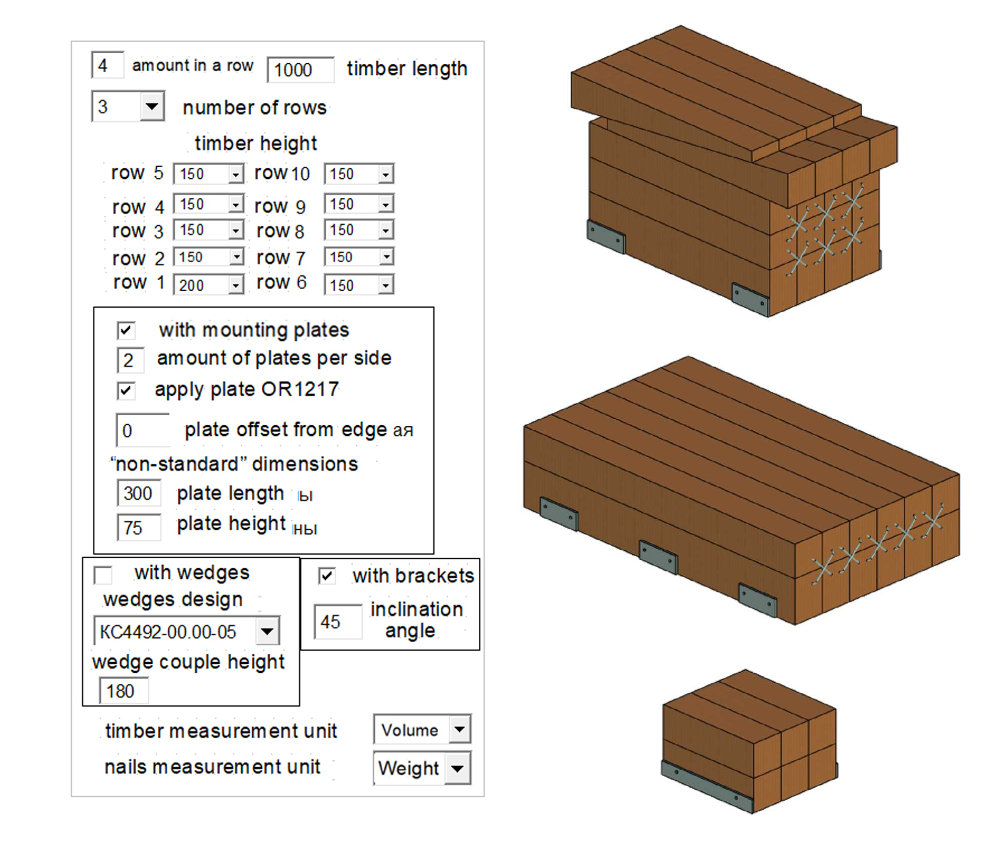
Figure 2 - Parameters dialog and configuration options for the timber pad model
The second similar assembly in the library of models of slipway tooling is a model of a timber pad. Such pads are used to support ship’s hull lines on a keel-block or another slipway support, meanwhile the timber is cut along ship’s hull lines. The assembly includes an array of timber models, wooden wedge couples and mounting parts (plates, brackets). A dialog has also been developed for setting parameters (see Figure 2).
This dialog is also divided into several sections. The first section contains parameters of the timber array: dimensions and quantity (in two directions), timber height is set separately for each row (for a more convenient choice of total height of the pad). Width of the timber for all cases is 150 mm. The second section contains parameters of the mounting plates: their presence, size and location (a user keeps an option to create plates of any size — for special cases). The third section manages parameters of additional elements - wooden wedge couples and clamps. In this case, the wedges are selected from database. The dialog also allows selecting units of measurement of timber and nails amount in the assembly structure (and specification, respectively). The timber amount can be calculated in cubic meters or pieces (timbers of different sizes are taken into account separately), and the nails amount - in kilograms or pieces. The figure shows several configuration options of the timber pad assembly.
The third model under consideration from the library of models of slipway tooling is the keel block model. It is designed in a different way: there is only one parameter set by a user – a variation name of the keel block (drawing number), all other variables are set based on a database that includes thirty-three variants, which differ not only in size, but also in configuration (model composition). As the result, development of a new version of the keel block is reduced to entering a new line into the database (of course, with verification of the obtained result). Some variants of the keel blocks are shown in Figure 3.
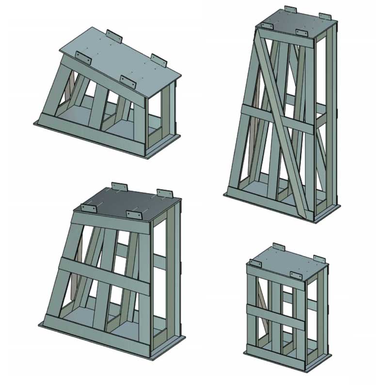
Figure 3 - Configuration options for the keel block model
Modeling of the slipway using the library of the slipway tooling models currently includes: lay-out on the working plane (creating 3D nodes for fragments attachment), fragments insertion from the library (as well as hull models, additional shorings and non-typical supports, if necessary), trimming models of wooden pads according to the hull model and modeling additional elements (ties, shorings, etc. - if necessary). An example of a slipway for assembling a trawler hull in a ship-repair shed is shown in Figures 4 and 5. Successes in this direction can be further built on by automating positioning of fragments, but this will require setting certain rules and imposing restrictions on design solutions, in order to avoid unnecessary complexity in setting the parameters of the assembly and fragments. Currently, this is not relevant, since there is no need to increase speed of development by reducing the constructions "diversity".
A scaffolding models library was developed in a similar way. It contains models of various types of scaffolding used at the enterprise (see Figure 6). Most of them are models of elements of collapsible rod scaffolding: racks, horizontal braces, diagonal braces, decking, ramps, etc. These models are greatly simplified and mostly include simple rods. This simplification is necessary because of the complexity of scaffolding assemblies – number of fragments in them can reach thousands. Figure 7 shows an example of scaffolding (of a bow) used in construction of a ship’s hull. In addition, drawing of scaffolding is practically a schematic diagram, and model detailing is not required. A detailed assembly of the scaffolding model is a very time-consuming process, so there are several standard assemblies in the library. Among them is a model of a scaffolding frame with a width of one cell, its length (number of cells in a horizontal row) and number of tiers are set by parameters. This model allows you to quickly build a straight "wall" of prefabricated scaffolding, but when building complex hull lines, you have to attach several "walls" with different heights to each other. Common assemblies also include a fence model — a set of horizontal rods and racks (with the option to disable them for a fence not on the upper tiers), applied to a rectangular contour, and models of metal decking of three and six shields. In addition to prefabricated rod scaffolding, there are models of other types of scaffolding elements — tower and cantilever, as well as models of wooden ramps.
The use of 3D models of scaffolding had to solve two tasks - to optimize construction of scaffolding when building complex hull lines and to facilitate calculation of number of elements of collapsible scaffolding. In general, these tasks were solved, but this modest progress was almost wiped away by the harsh reality that posed three problems to the user (when designing large-area rod scaffolding): a lot of time taken to create an assembly, "weakness" of the computer, and complexity of subsequent modification of scaffolding (all fragments turn out to be connected to each other). Based on the practical experience, it can be concluded that scaffolding automatic modeling with a help of a library of standard models is possible only for relatively small assemblies - models of local scaffolding, without thousands of fragments. Design automation of large-area scaffolding must be brought to a new level, inaccessible to the author of these lines personally - building of a special application in the T-FLEX CAD environment, which will provide generation of fragments in an assembly according to specified rules, creation of projections for the drawing and counting elements. To solve this problem, the developer company of T-FLEX CAD "Top Systems" was involved, which constantly cooperates with the VS and provides invaluable assistance in mastering the system and solving actual tasks of the enterprise. Currently, a special plugin is being developed, the use of which should significantly reduce labor costs for designing complex scaffolding (this will be discussed in a separate article).
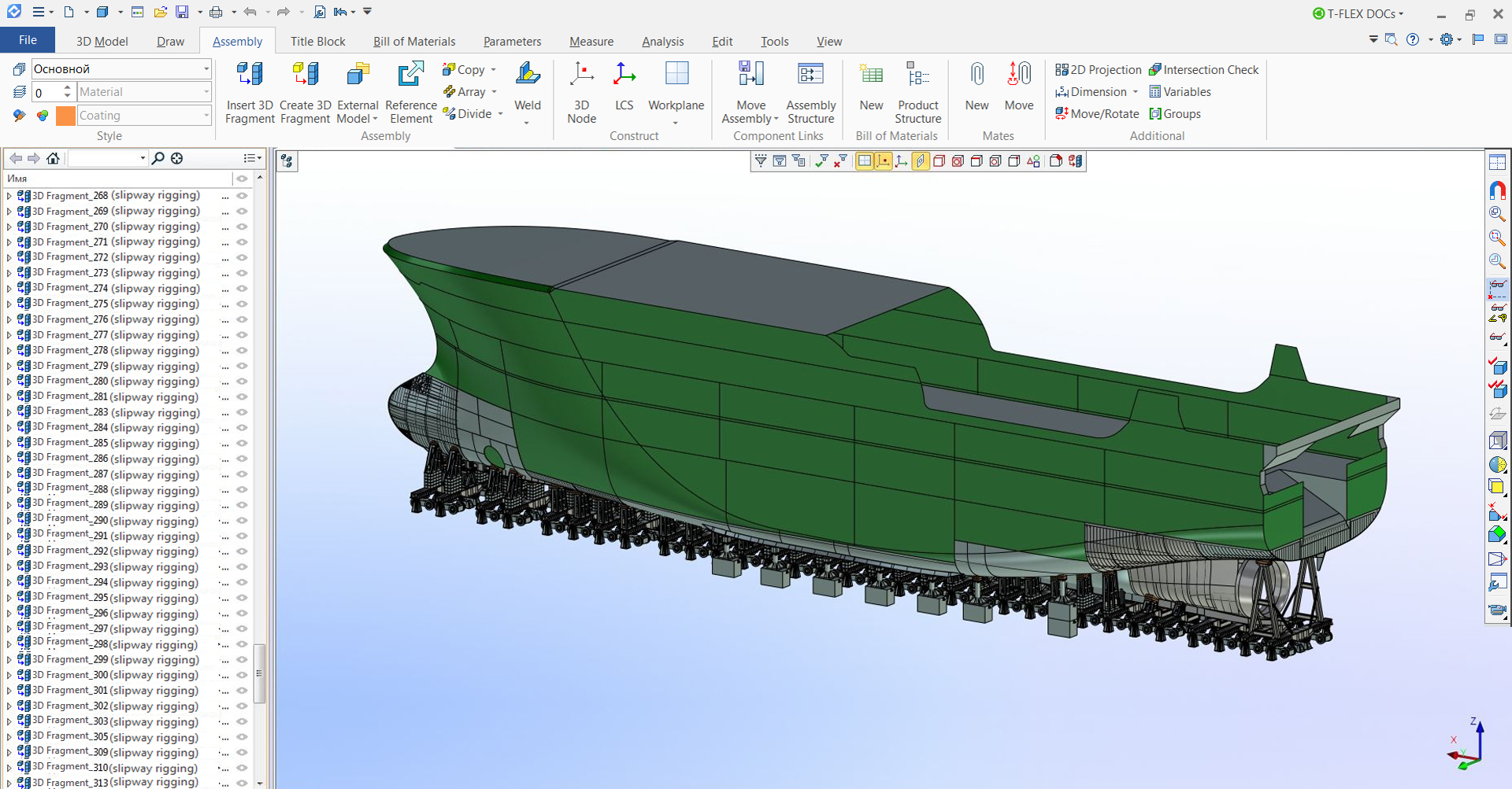
Figure 4 - General view of a ship assembly slipway
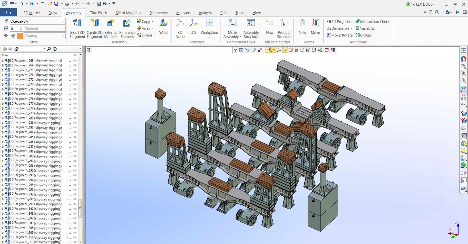
Figure 5 - Fragment of a model of a ship assembly slipway
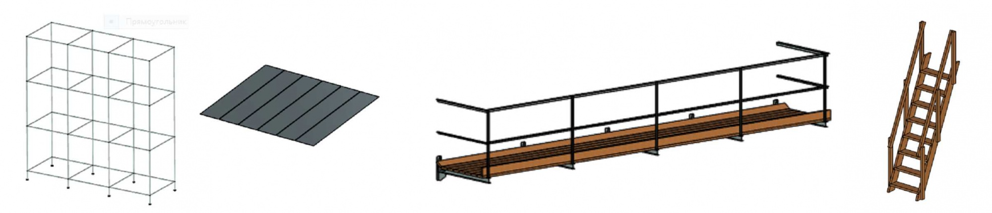
Figure 6 - Examples of models of scaffolding nodes
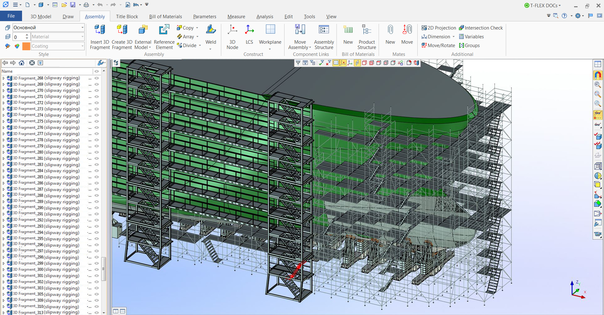
Figure 7 - General view of the bow of a scaffolding during the construction of a ship's hull
A library of models of metal structures is the third of the ones used in work, and probably the most relevant. It supplements regular T-FLEX CAD libraries and contains models of frequently used grades of rolled metal product. Models from this library are used in designing of various metal structures: technological support and transport frames, structures for various purposes, racks, etc.
The most complex model in this library is a model of a standard rolled steel angle. Its feature is ends trimming of the angle during insertion into the assembly. Trimming can be done in two ways: by an angle (set by a user without restrictions) and by adjoining to another angle (parameters of a trimming profile are set by a user). Both ends of the angle can be trimmed, moreover, in different ways – only one flange is trimmed at each end. The model contains a database, which includes the most commonly used standard sizes of both equal- and non-equal-flange angles. This model allows you to quickly assemble frames from the angle without additional operations for the design of angles adjunction.
The second model also refers to a rolled steel profile - this is a channel beam model. Also, the model provides a choice of three design options - a single channel, two channels "as a box", two channels "as an I-beam". In addition, it is possible to choose a type of channel - with a slope of flanges or with parallel flanges, as well as to set a typical size and length. This model is used in design of various technological frames and structures. Other than profiles, there are two models of sheet materials for non-slip decking - a sheet with diamond-shaped surface ribbing and an expanded sheet. These models are used in a limited way, mainly to create images with high model detailing, due to presence of large arrays of small elements in them. To facilitate the work, a model of sheet with surface ribbing has an option to exclude ribbing. The described models are shown in Figure 8.
The other models in this library are relatively simple models of profile bar, bracket knees, etc. In the future, it is planned to expand this library with a set of adaptive fragments for building metal structures based on previously created 3D nodes, with a possibility of automatic trimming of mated parts by a profile. It should significantly reduce number of user actions when creating an assembly, and therefore reduce complexity of modeling.
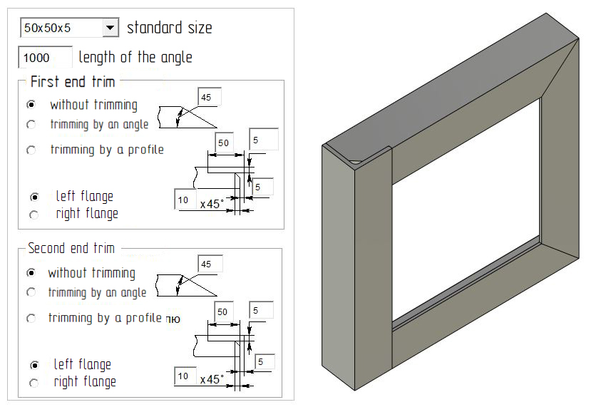
Figure 8 - Examples of models of metal structures
Design of rack and pattern assembly jigs is one of the key areas in which the implementation of 3D models was required to reduce labor intensity. A jig in shipbuilding is a set of supports (racks or patterns) on which a section of a hull is assembled. Design of the jig at the same time consists in defining locations of the supports and calculating their exact height. The use of two-dimensional projections of a drawing for this work imposes restrictions on possible spatial positions of the section during assembly, and also requires increased attention and accuracy when creating constructions. When it became possible to use a 3D model as a "primary source" of the hull geometry, bypassing the two-dimensional drawing, a task was set to automate the process of designing the jig. This task was successfully solved with the help of T-FLEX CAD developers, who created a plugin for the VS that performs all the constructions for calculating the height of the supports (this will be discussed in a separate article). A user's task was to prepare the model of the section, place it in the right way and specify location points of the supports. To use this technology, the company has developed a methodology that includes a description of the entire process: preparing a model, working with a plugin, modeling patterns. This technique has been mastered and successfully applied already on several orders, while a significant reduction in the complexity of the design has been achieved. In this case most of the time can be spent on preparing the model (with complex geometry and splitting a plating into sheets). Reducing the time to prepare a model is a separate task and is associated with importing models of hull sections. And this problem should be solved, most likely, no longer within the enterprise, but in cooperation with a designer who develops a ship model in shipbuilding CAD and transmits it through a neutral format.
It can be concluded that since the introduction of T-FLEX CAD at the enterprise, it has become possible to significantly automate the developing of technological equipment in some main areas, reducing labor intensity and increasing productivity of the EPPD. It is also important to note that part of the automation work is done by the enterprise, but a lot of help was provided by the employees of CJSC “Top Systems”, who have been providing support since beginning of beta testing. Staff of EPPD hopes for further development of the T-FLEX CAD system, further mutually beneficial cooperation and eventually improvement of the quality and productivity of work!