Designing a business jet aircraft in T-FLEX CAD
Author: Alexander Makarov, Top Systems Ltd. Implementation Department Lead Specialist
On the point of the T-FLEX CAD 17 release Top Systems Ltd. presented an article describing the creation of one of the most complex and interesting models – business jet assembly. New functionality introduced in the T-FLEX CAD 17 and its application will be described in separate articles. This is neither a methodology guideline, nor a lesson. The article shows the general conception of solving such task by our specialist. The resulting model is the demonstration, which is used for adjustment of design technology in aerospace industry.
The work started from the general idea of creating a small business jet with specifications similar to the Cessna Mustang and Embraer Phenom 100. At first, there were just conceptual sketches on paper. The main concept, general design principles, key specifications and main dimensions were defined.
Modelling in the T-FLEX CAD started from creating the aircraft structural layout file and defining the general strategy. The layout file contains basic support geometry, which should be referenced by fragments of the aircraft dependent on the external aerodynamic surface.
The general strategy stated that the aircraft should consist of six main sections: cockpit, fuselage, wing, tail and two pylons with engines. Each section was modelled separately, but all of them were referencing the same layout.
So, the aircraft main view file was created. Sketching was done using the new spline creation mechanics, which allows dynamic definition of elements’ tangency. It provides mathematically “smooth” aerodynamic surfaces (Fig. 1). Moreover, the preliminary frames positions were defined using construction lines. I.e. the layout utilizes the so-called hybrid parametrization.
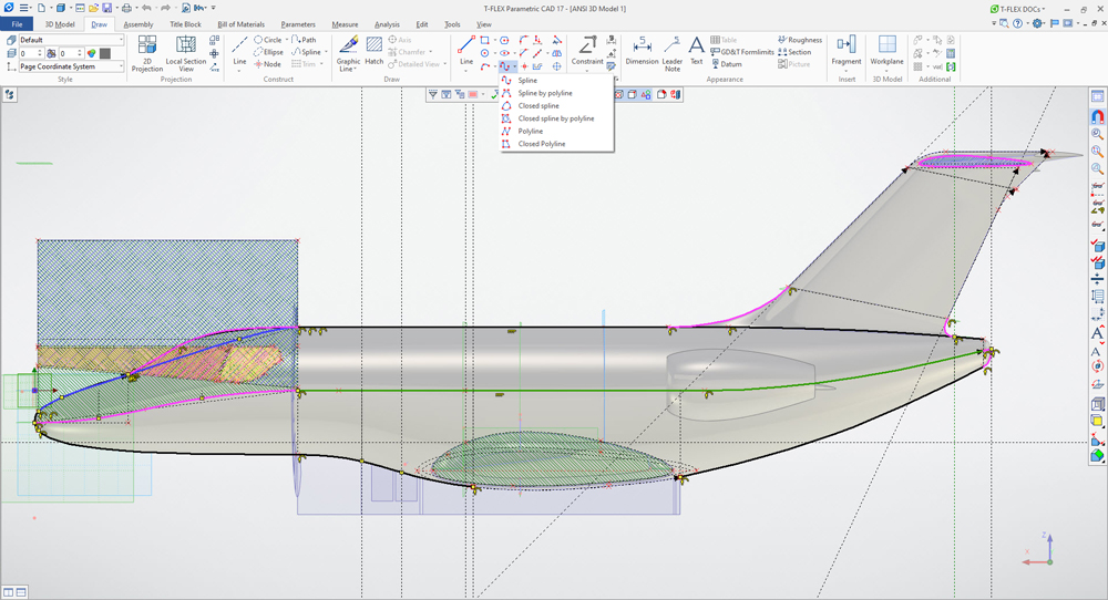
Fig. 1. Using the new T-FLEX CAD spline mechanics.
It was decided to make the max precision solid model of the whole aircraft first (Fig. 2), which then should be used for easily carving out airframe parts and positioning them in relation to the main assembly origin.
Considering the high variability of the cross-section along the aircraft’s length, the Parametric Sweep (Body by Parameters) was used as the main operation defining the shape of the cockpit. It also defined shapes of the belly fairing and the wing-fuselage fairing.
Cockpit windows were made using the Loft operation. The window’s projection was cut out of the main parametric sweep, then edges of the resulting body were used as section and guides for the Loft operation along with defining their tangency to cockpit and fuselage surfaces. The wing and tailfin were created using the Sweep operation.
Fairings (wing-fuselage, tailfin-fuselage, tailplane-tailfin) worth special notice. Variable-radius fillets were used. Splines tangent directly to surfaces were selected as guides for Loft operations.
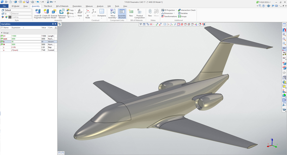
Fig. 2. Aircraft main view. T-FLEX CAD solid model.
Since cockpit, fuselage, wing and tail were modelled separately, the layout file was adjusted for each separate section, while staying intact in terms of basic support geometry. It allowed to decrease the overall number of operations and make dimension chains more recognizable.
Most airframe parts (frames, stringers, spars, ribs, skin panels) were carved out of the solid model of the whole aircraft. Workplanes for positioning of airframe parts were created in layout and used for splitting the solid model. The updated T-FLEX CAD reference elements mechanics was the main tool that allowed flexible customization of fragments regeneration upon parent elements change (Fig. 3).
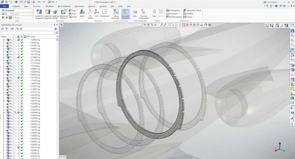
Fig. 3. Frames in the T-FLEX CAD layout file.
Despite the fact that airframe contains various types of parts (stamped, milled, composite), all of them were modelled using the same algorithm:
– Carving a basic body out of the main view solid model;
– Creating a skin offset;
– Applying radii for stamped parts;
– Creating main thicknesses of a part using the Shell command;
– Creating main holes and cut-outs using auxiliary planes;
– Applying tool radii for milled parts;
– Adding or editing paths, which define crossing elements (stringers, spars) in the layout file, referencing them in fragments;
– Precise cut-outs positioning;
– Positioning of fasteners using auxiliary planes and path’s projections;
– Drilling holes for fasteners;
– T-FLEX Analysis calculations;
– Gaps and clashes check (Fig. 4).
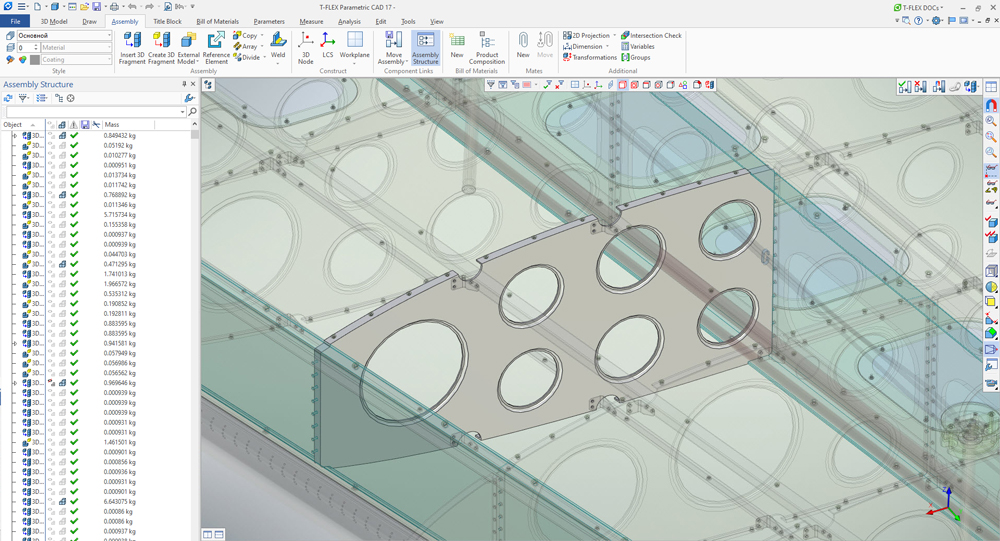
Fig. 4. Typical wing frame element in the context of the T-FLEX CAD assembly.
So, the airframe was created. Besides, linking elements (brackets, clips, etc.) and load-bearing panels were added. The work on similar linking elements was done quickly, thanks to the smooth parametrization mechanics. It required changing only a few parameters, then a bracket or a clip was automatically regenerated fitting a corresponding frame shape.
Then the airframe was fitted with main units and mechanisms of fuel, hydraulic, air conditioning and ice protection systems. Electrical units, radar, crew seats, interior lining and lights were added to the cockpit.
The fuselage was fitted with passenger cabin, toilet, interior lining. The tail section was fitted with the service tank and its pumps and filters, the turboexpander, valve units, etc. The centerwing and wingboxes were finalized. The landing gear, containing variable-defined position options, was installed. Some elements were edited in the context of the assembly to ensure the optimal placement (Fig. 5).
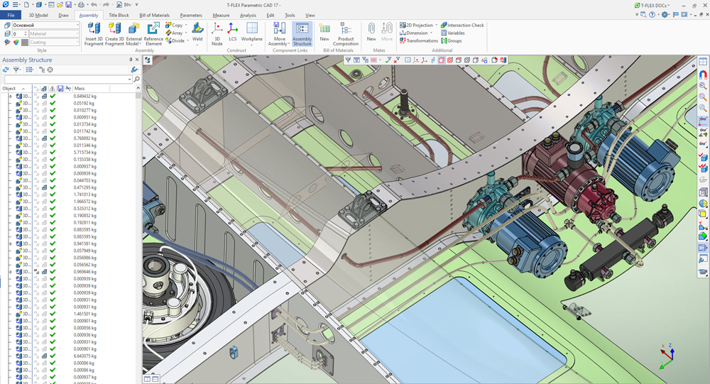
Fig. 5. Electrical engines and fuel pumps in the centerwing of the T-FLEX CAD assembly.
The special attention was paid to piping attachment points. In each section of the aircraft they were calculated in advance and marked by external 3D nodes. This provides, for example, the precise connection of bleed air ducts to valves of air conditioning and ice protection systems in the tail section (Fig. 7).
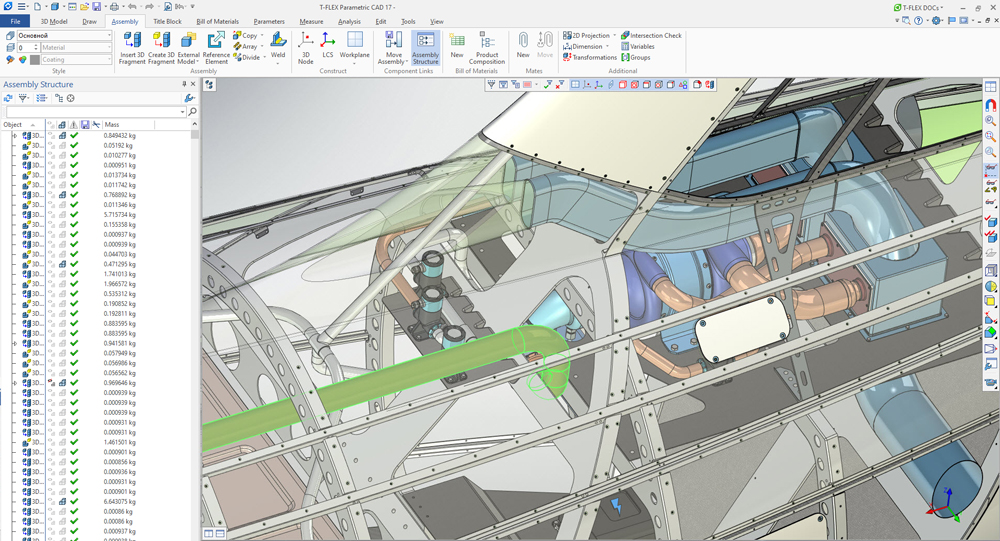
Fig. 6. Piping in the tail section of the T-FLEX CAD assembly.
Next, the piping itself was generated. Along with pipes, associated elements were added, such as flanges, fittings, various drain valves.
The piping was created in the assembly context using the improved T-FLEX CAD routing mechanics and pre-made nodes in brackets and clamps.
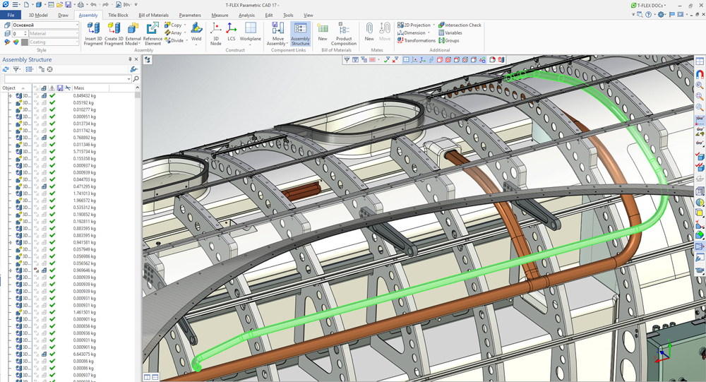
Fig. 7. The pipe of the ice protection system highlighted in the in the T-FLEX CAD fuselage assembly.
After creating the airframe and installing main equipment and pipes, we started to enhance the assembly level of detail by installing exterior lights along with their electrical connections, various attachments, wiring brackets, door lock mechanisms, etc.
Passenger compartment windows were initially marked in the fuselage layout, then projected onto the support geometry and cut out using the extrusion with Boolean subtraction in the context of the new file. Since the window consists of multiple layers, it only required to adjust the Shell command parameters for each layer after creating the initial Boolean operation. Then we modified resulting fragments, subtracted the interior volume, applied materials, etc.
The door and emergency exit were modelled in the similar way.
Aircraft control surfaces modelling worth special notice. Flaps, ailerons, rudder and elevator actuators’ mounting points had to be correctly transferred from the aircraft structural layout file. Due to the fact that all control surfaces are assemblies, individual layout files were created for each control surface (e.g. flap). Mounting points were transferred from the main layout file to the flap layout as reference elements and used for positioning of actuators and other components. So, the flap was modelled in its own pre-defined environment.
While flaps were designed in traditional way with aluminium spars and ribs; rudder, elevator and ailerons were made of composite materials with honeycomb core. Each layer of a core was created in the following way: a cell was extruded, multiplied using a linear array and a resulting body was used in intersection with a result of applying the Shell command to a control surface’s layout (Fig. 8).
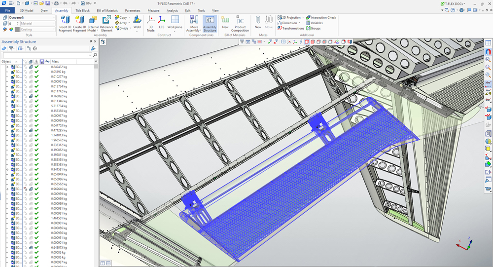
Fig. 8. Composite rudder with honeycomb core in the context of the T-FLEX CAD tail assembly.
The skin was preliminary marked and cut out from the basic solid in the same way as other airframe elements. Holes were drilled on-site using corresponding holes in other airframe elements as coaxial holes.
Multiple manholes in wing lower panels were effectively designed by projecting profiles onto the skin in the context of the wing assembly.
Projections of profiles were also used, when creating cut-outs for air conditioning system intakes. Intakes themselves were designed using the Sweep command (from cut-out in the skin to the heat exchanger’s flange).
Fasteners were installed in three stages for each section of the aircraft: riveting the main frame, creating equipment attachment bolt and screw joints, riveting the skin. The array of bodies usage made fasteners installation more comfortable and slightly sped up the work.
All design stages mentioned above were sequentially applied to each section of the aircraft in compliance with the common layout file. Then the cockpit, fuselage (Fig. 9), wing, tail and pylons with engines were finally combined in a common assembly.
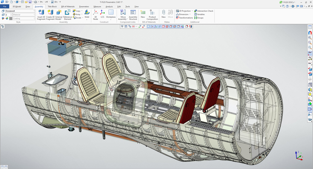
Рис. 9. Aircraft section example. Fuselage in the T-FLEX CAD.
All elements and mechanisms, which have several possible positions, were put onto a special layer or connected to variables in the common assembly. Thus, it is possible to open doors, extend landing gear, change the skin colour, etc., from the main assembly (Fig. 10).
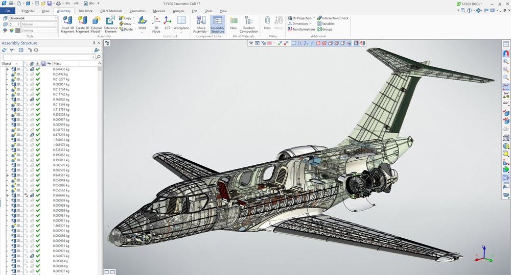
Fig. 10. Finished aircraft assembly in the T-FLEX CAD
Convenient mechanics, high working speed and overall elaboration of T-FLEX CAD functional capabilities were the key to designing the whole aircraft (except engines design) in about 40 weeks, 8 weeks per section, including all the internal parts and equipment (Fig. 11). By the way, the aircraft assembly consists of about 49 thousands of components.
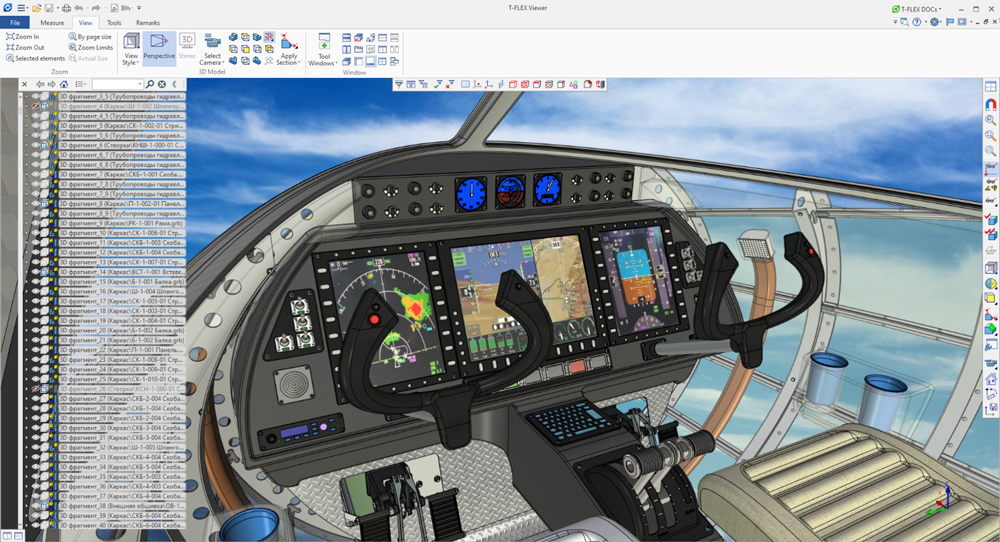
Fig. 11. Cockpit interior in the T-FLEX CAD
The engine with pylon was designed in about six weeks (Fig. 12).
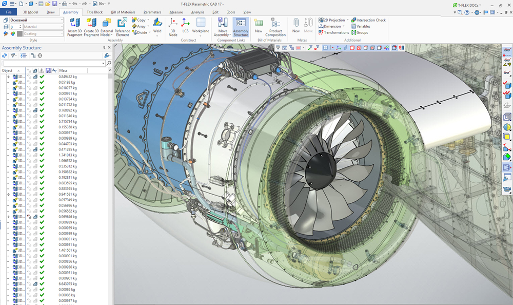
Fig. 12. Engine assembly in the T-FLEX CAD