What's new in T-FLEX CAD version 11
- What's new in T-FLEX CAD version 11
- Changes in User Interface
- Changes in 3D Modeling Commands
- Working with Assemblies
- Working with Drawings
- System Performance Enhancement
- General Changes
- Spelling Check
- Libraries
- Layers management
- Custom commands
- Variable Editor
- New Tool Window to Work with Variables
- New "Group" Variable Parameter
- Customizing the Variable Editor
- Printing Capability
- Multiple Selection of Variables
- Copying-Pasting Variables
- Stepwise Undo/Redo of Actions
- "Properties" Command for a Variable
- Error State Diagnostics
- Capability to Define Names for Connector Values
- Express Analysis
- Export/Import
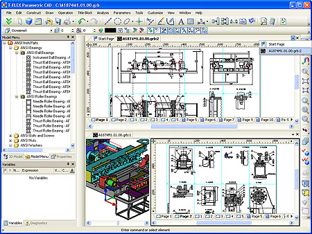
This page presents a review of new functionalities, capabilities and improvements of
Changes in User Interface
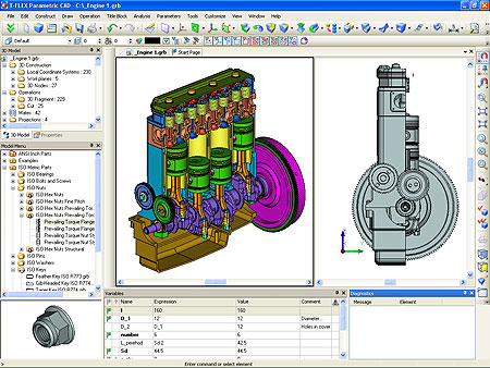
In the development of T-FLEX CAD 11 special attention was paid to enhancing working comfort and to improving the user interface. The interface became more elegant and modern, its ergonomics being significantly improved and more free space arranged in the screen to perform the primary system tasks.
New Style Appearance
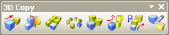
The system has received a new, modern appearance. The appearance matches the layout theme defined for the operating system. New full-color command icons have been developed for the system. The icons have two sizes (16 x 16 and 24 x 24). The size can be automatically selected depending on the current screen resolution set in the computer, or can be defined by the user at any time.
![]()
![]()
Main Bar
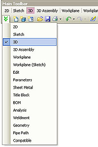
The main element of the system's user interface has now become the "Main Bar" - a new toolbar with extended capabilities.
![]()
The main bar has predefined sets of commands which can be selected by the user or get activated by the system automatically depending on the currently performed task and system settings.
The contents of the main bar are oriented at performing various tasks - drafting, 3D modeling, analysis, drawing on a workplane, sheet metal manipulations, BOM editing, etc.
Additional applications that are installed to work together with T-FLEX CAD, load their own specialized sets of commands into the main bar to address respective functions. For example, the
A user-selected set is remembered in the current document window and will be automatically restored whenever this window is activated. This setting is saved with the document file and is activated whenever the document is opened.
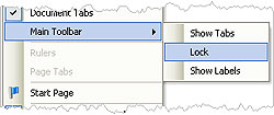
The user may enable the display of labels under the main bar's buttons as desired. This is convenient when getting initially acquainted with the system or when working with high resolution screens.
![]()
For those users who got accustomed to work with former sets of main bar buttons, there is the provision of the "Compatible" set as the main bar used to have in previous versions. If necessary, one can freeze any set to avoid switching to other sets when various commands are launched. To freeze a set of buttons on the main bar, call the context menu by right-clicking ![]() and select the command "Main Bar/Fixed".
and select the command "Main Bar/Fixed".
Toolbar Improvements
Some command buttons are grouped within toolbars on the basis of their performed function similarity. Upon clicking the right-hand side of such a group button, a toolbar dynamically opens, in which you can finally select the desired command. This temporary toolbar can be made permanent by dragging it to the screen beyond the title area. After that it can be placed anywhere in the screen.
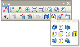
"View" Toolbar
To manage the display modes of a document's views, snapping modes and other view parameters, and the "View" toolbar has been created, which does not change its contents when switching between documents and views. This toolbar contains drop-down toolbars to control various parameters. Those include, for instance, the toolbar to control object snaps and the toolbar to manage view points.
Customizing the User Interface
- customizing buttons placement in the toolbars;
- editing of button images;
- the capability of displaying a tooltip text directly on the button;
- customizing the contents of the textual menu;
- editing the menu text;
- the capability to add menu items to bars;
- hiding seldom used menu items;
- the capability to create custom bars;
- the capability to create user-defined custom commands to launch macros, applications, to open documents, to open folder and library windows to manage files.
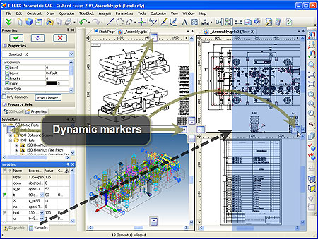
Managing Tool Windows Placement
The tool windows placement mechanism became more convenient. New ways of grouping tool and working windows have been added. When windows are being dragged, there are dynamically displayed marks helping to define the new position. When the pointer with the dragged window approaches a mark, the preview of the new position is displayed as a transparent box.
The operation of "pop-up" windows appearing along the perimeter of the main system working window has become more convenient.
The variable editor window is being moved to the right part of the screen
Managing Pages
Page management tools have been improved in the system. The page tabs can now be positioned either at the bottom or at the top part of the document window. One can use the context menu accessible at a page's tab. The context menu provides for sorting pages, deleting pages, creating a new page at the desired position, renaming a page. The order of pages can be changed by simply dragging a page's tab to the desired position. Introduced are the new types of pages - "Text" and "BOM". The document page status (the command Customize|Status), the "Colors" tab, allows to use a mode in which the background color is applied only within the page borders.
"Welcome" Window
When the system is started, the "Welcome" window appears on the screen. It contains the list of recently opened documents, the list of templates to create new documents, and a pane with useful links.
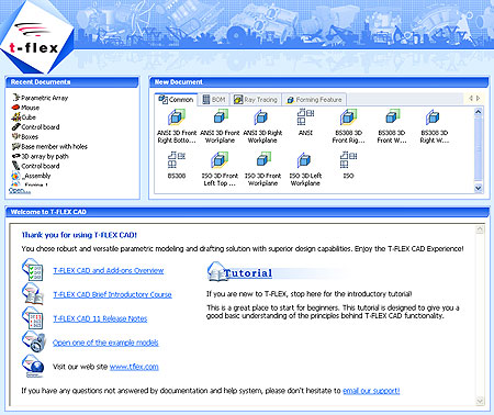
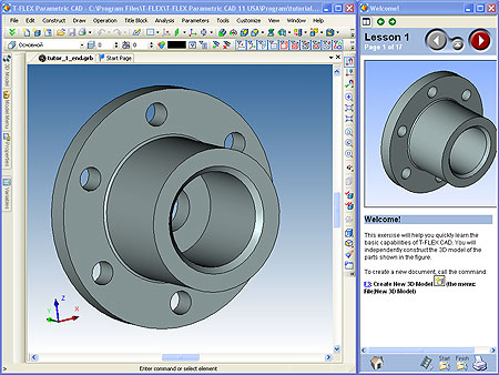
Tutorial
A tutorial has been developed to help beginner users master the system. It presents a set of theme lessons which will take the user step-by-step through the studied functions and will teach to work with main system's tools.
One can review the lessons in a separate reference window simultaneously with working with T-FLEX CAD system. In this way the user can independently repeat each step of a lesson. To assist the comprehension, each lesson contains a video clip and two models - the initial and the final one.
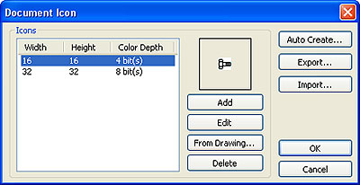
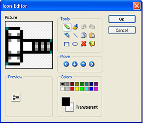
Editing a Document's Icon
A new built-in document icon editor is provided within the system. It serves to create and edit the icons displayed in the document and library menu lists, in the File Manager, in the document window title, etc.
The icons editor supports various formats and an icon's color range, import/export of images from various bitmap formats, as well as automatic creation of icons from the drawing image or from the 3D window image.
Improvements in Command Dialogs
The edit boxes used in properties dialogs are now enabled with the preview of special symbols and formatting (fractions, indices, etc.). Whenever a new value is entered for a string text as a special-convention combination of symbols, a special tooltip window appears with the preview of the resulting appearance of the text.
![]()
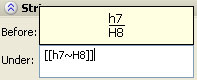
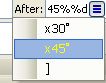
The drop-down lists of values accessible through the button next to the edit box now also display the formatted lines with special symbols.
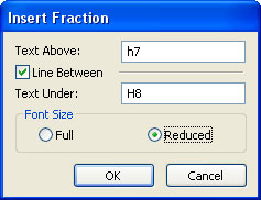
Fractions can be inserted into an edit box using a special dialog accessed through the dedicated command in the context menu.
Managing Document Windows
Improvements have been made to main working document window controls. The windows can be grouped by dragging the tabs to the right or to the bottom part of the system main window. Groups can be positioned horizontally or vertically. There are separators between groups which serve to change a group's width. The order of document windows within a group can be changed by simply dragging document tabs. Document windows can now be managed using the context menu accessed at a desired tab.
If necessary, one can switch to the "classic" way of working with the multi-document interface. To switch, disable the document tabs in the context menu accessed by right-clicking ![]() in the area of toolbars.
in the area of toolbars.
Changes in 3D Modeling Commands
New Version of Parasolid
The system uses the new Parasolid 19.1 version with added new functions and improved algorithms of performing solid body operations. The special-case processing has been improved in a number of operations. For example, the Y-blend function now supports the blend creation despite small faces standing on the way which disappear after blending, or the edges that make excessive subdivision of the blend surface. In earlier versions this could fail the operation.
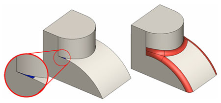
A small face may disappear through the blending
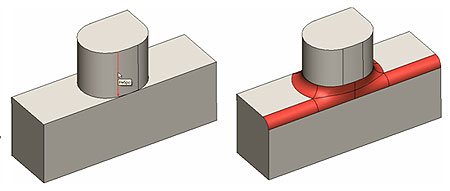
An extra edge does not fail the blend
Deformation Commands
A new group of commands is introduced in the system for the 3D modeling which allow changing the shape of solid or sheet bodies by various "deforming" manipulations. The new group of commands is located within the menu Operations|Deformation. Common for these commands is the method of obtaining the result. Based on the parameters defined by the user explicitly or with the special draggers, an internal function is created within the body being modified, which deforms the body's surfaces. At the time of defining the initial conditions the preview is active which helps assess the correctness of the operation parameters' definition. By applying the deforming function, the entire source body or a part thereof is continuously modified. The topology of the deformed part of the body doesn't change, which means the original number of faces, edges in the vertices is maintained. If necessary, faces and edges of special types (planes, straight line segments, cylinders, circular arcs, etc.) are automatically replaced with spline surfaces and curves.
Skew
This deformation type implies the existence of a coordinate system in which the 3D outline box is calculated. One can use either a local or the world coordinate system. The deformation law is defined by moving the vertices of the outline box in various directions.
The vertices can be moved along any of the coordinate system's axes, along the edges of the outline box or along the diagonals of the outline box's faces.
To help defining the movement of the vertices for the skew, there are special draggers which appear when the mouse pointer approaches a vertex of the outline box or upon clicking at its vertex. Two types of draggers help moving the desired vertex either along the edges/diagonals of the outline box or along the axes of the used coordinate system.
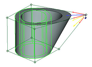
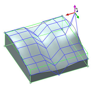
Sculpt Deformation
This deformation type allows to define a regular mesh of points on one of the faces of the outline box, which is calculated relative to a selected coordinate system. Any point on this mesh can be moved relative to its original position by the user-specified amount. The movement is performed using a three-dimensional dragger. The user may select and move several points simultaneously. As a result of moving the mesh points, the flat face of the imaginary outline box is transformed into a 3D spline surface which constitutes the law of the body transformation required by the user.
The sculpting deformation operation has three modes:
- one-sided, where the points that move are all located on one face of the box;
- two-sided, where the points located on the opposite faces of the box move simultaneously. The points on the face opposite to the selected one move in the same direction and for the same distance;
- symmetrical, where the points on the opposite faces of the outline box move symmetrically with respect to the symmetry plane of the box.
Original Model |
One-Sided Mode |
Two-Sided Mode |
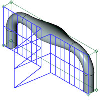
Symmetrical Mode |
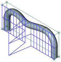
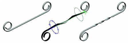
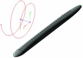
Scaling/Twisting
The scaling/twisting operation allows to define the scale and the twist angles in the intermediate sections along the axis of a selected coordinate system. There can be different scales in the different coordinate axis directions. The deformation can be applied to either the entire body or within the boundaries of a user-defined zone.
Besides scaling and twisting the sections, one can stretch or compress the deformation zone in the direction of the selected axis of deformation. In this way one can elongate or shorten portions of bodies.
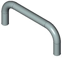
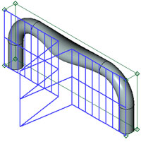
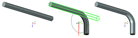
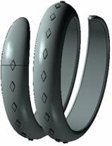
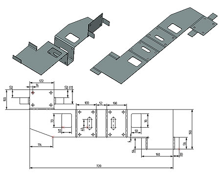
Bending
The bending operation allows to bend a selected body with respect to a selected axis by the specified angle. Besides the bending angle, the distance to the "neutral" surface shall be specified, which is the surface whose points are not subjected to stretching or compressing deformations. Another required initial parameter to be defined is the plane dividing the source body into the bent and unbent portions, which will define the beginning of the bend zone and the reference point for the bend angle. Another option supported by the operation is the use of two-sided bending by the specified angle with respect to the dividing plane.
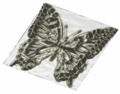
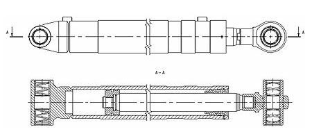
Deformation by Surface
This type of deformation creates the law of mapping between two surfaces and applies this law to the original body. Input data includes sources and target surfaces and three pairs of points for correct positioning. The result can be offset from the target surface. This type of deformation works in two modes - "By Parameters" ? "Minimum Distortions". First mode uses exact correspondence of the surfaces by selected points. Second option retains proportions of the geometric distances.

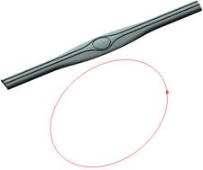
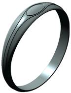
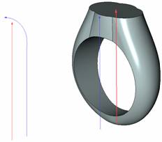
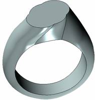
Deformation by Curve
For this deformation the mapping law is defined by two curves, the original one, associated with the source body, and the target curve. User has control over positioning the result relative to the curve. Three different options help to solve various typical tasks.
- 3D Curve - 3D Curve. This option uses one source curve and one target curve. In most cases the source curve is a straight line. One of the examples is folding the original lengthy body into a ring. The resulting body can be set as closed.
- Curve - Spiral. The target curve is presented as a spiral curve with axis. This option differs from the previous one by method of controlling the body position regarding the curve.
- Pair of Curves - Pair of Curves. Additional curves define twisting law of the result regarding the main curve.
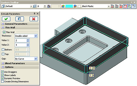
Dynamic Preview of the Operation Result
The capability for dynamic preview of the operation result is introduced for basic 3D modeling commands (Extrude, Rotate, Sweep, Pipe, Bend, etc.). The preview is automatically recalculated and refreshed in the screen upon selecting the source elements to perform an operation and upon modifying parameters via the properties dialog or a dragger. Meanwhile, the current material's properties are accounted for.
If necessary, this capability can be deactivated in the "Options" tab.
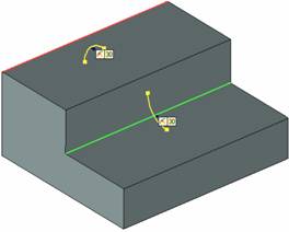
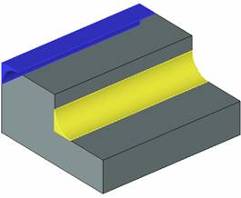
Preview Changes in 3D Operations
There is a new preview mode in modeling operations that allows seeing modifications of geometry prior to confirmation. In this mode the yellow color marks volume that will be added to the original body and blue color shows the subtracted volume.
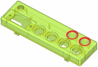
Compare Models
The new command "Check Model Changes" compares two bodies and marks the difference between them. It also calculates the volume of difference that may be helpful in analyzing such difference. The command can compare various states of the same model in process of its creation, model configurations on parametric changes as well as two arbitrary bodies.
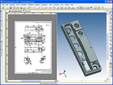
2D Projections
Calculation of 2D projections for producing drawing views from the 3D models was optimized. In many cases 2D projection creation and update takes fewer time and less computer resources. New types of 2D projections were added.
New Types of 2D Projections
T-FLEX CAD 11 now has much wider set of 2D projections along with the existing projections that consist of image lines:
- Precise (Image Lines). This type corresponds to the 2D projections existed in the previous releases.
- Vector Picture. The image of this projection fully corresponds to the "Image Lines" type. At the same time lines are not created and projections exists only as a picture. This type helps to shorten regeneration time and to reduce memory usage that can be helpful for very large models.
- Rendering. The image corresponds to "rendering" mode of the 3D view.
- Shading. This projection corresponds to "shading" mode of the 3D view.
- Wireframe. This projection is drawn as a wireframe and corresponds to the similar mode of the 3D view. This mode supports "Remove Hidden Lines" option.
All new types of 2D projections support further usage of these projections for detailing. New elements (dimensions, leader notes, etc.) will be created with the same commands as for 2D drafting and will look the same but will be connected directly to the 3D model objects. Hatch will be generated for the sectional view in the plane of section. It is possible to modify the properties of these hatches. New types of projections does not support 3D construction elements and direct modification of the lines (parameters, removing).
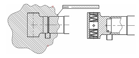
Accounting for Line Types when Creating Local Section Views
The capability to account for the types of graphic lines in the source hatch's boundary is introduced in the local section view creation mode of the 2D projection creation command. If the graphic lines are of the waves or another user-defined type other than straight geometry (for example, a zigzag), then this geometry will be accounted for when creating a local section view. The capability to account for a line type can be activated or deactivated in the local section view's parameters dialog.
Accounting for Gaps when Creating Sections and Cuts
The gap (if any) in the source projection is accounted for when creating a section or a cut based on a 2D section (the section line).
Capability to Obtain the Bend Axes
When creating a projection view of a body produced by unbending a sheet model, the system automatically creates the projections of the bending axes if the axis creation option is active.
Workplane Display
The "Transparency" parameter is introduced among the workplane properties. The variation of this parameter affects the degree of transparency of a workplane as displayed in the 3D window. The degree of transparency can be varied in the range from zero (fully opaque) to 1 (fully transparent). If necessary, the semitransparency can be suppressed in the OpenGL parameters settings (the command Customize|Settings, the tab [3D], the button [OpenGL�]).
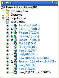
Improvements to Model Tree
The user gained the capability to customize the model tree in order to display additional information for objects of various types. In the context menu accessed by right-clicking an item ![]() in the model tree, a new "Appearance�" command is introduced. Calling this command brings up the representation settings dialog.
in the model tree, a new "Appearance�" command is introduced. Calling this command brings up the representation settings dialog.
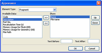
This customization not only helps view the model tree in a way convenient for the user, but also make the optimization of the 3D model with respect to the recalculation speed and memory use. Now the system can display such information next to an item, as the time spent by the computer to recalculate it, the amount of an item's geometrical data into memory and the amount of data required to draw it (the meshing information).
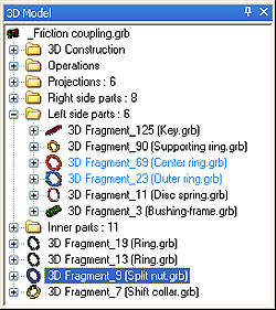
When working with assembly models, the information about the name and designation code of assembly components used in BOMs is quite helpful. This information can be displayed together with, or instead of, the name and path to an assembly component file.
The settings defined in this dialog are saved in the document file and are used whenever the document is opened.
It became possible to create folders for Bodies of the 3D model in the model tree. To do this, from the context menu call the command "Move to folder". If the folder is already created in the 3D model tree, then Bodies can be moved within the tree using the mouse. In this way, for example, one can additionally group the Bodies (3D fragments) of an assembly model into folders based on their association with the mechanisms or logical groups.
Working with Assemblies
2D Fragments
Commands to Create and Edit Fragments
Significant improvements have been made to commands of 2D fragment insertion and editing. The command interacts with the properties window which allows to define in the transparent mode fragment parameters, as well as the options of the command itself.
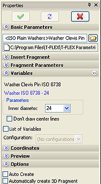
The dialog to work with the active fragment's variables can now be positioned either inside the properties window or in a standalone window. Just like other tool windows, the standalone window of fragment variables can be floating or can be docked along one of the main system window borders. To isolate the variables handling section into a standalone window, click the button ![]() . To return to the initial state, close the standalone window.
When creating or editing a fragment, the transparent editing of variables is now made available by clicking in the field of the variable value in the drawing. For example, upon inserting the format frame, the variable values can be edited directly in the drawing field even before its creation is confirmed.
. To return to the initial state, close the standalone window.
When creating or editing a fragment, the transparent editing of variables is now made available by clicking in the field of the variable value in the drawing. For example, upon inserting the format frame, the variable values can be edited directly in the drawing field even before its creation is confirmed.
The mode of automatic creation confirmation after inputting the snap points helps speed up the creation of simple fragments. This mode is activated with the new option "Auto Create" in the special [Options] section of the fragment's properties window.
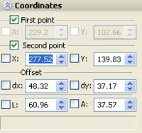
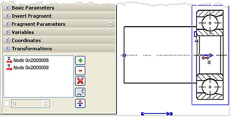
The coordinates of the fragment's snap points can be edited directly whilst inserting or editing it, similar to how this is done when creating a sketch. To work with the coordinates of snap points, the special [Coordinates] section is provided in the properties window. A new capability is introduced to define additional transformation of a fragment inserted using the snap vector or a connector - a special system element helping to connect parametric parts within an assembly. Additional transformations can be defined by using either constant values or my variables or other model elements. For example, one can use the drawing's lines to adjust the fragment's position. Additional transformations can be defined either by using buttons in the dialog or by the draggers located at the start point of the fragment's fixing vector. As the pointer approaches the dragger, it assumes the specific shape corresponding to the transformation axis. After clicking the left mouse button on the dragger one can define a new transformation by dragging the fragment to a new position. Dragger displayed as a coordinate system helps to assign additional transformations. Its colors correspond to the colors of coordinate system axes in the 3D scene.
When using connectors in creating an assembly drawing, the user can first define the required rules of insertion for the connector in the fragment file, by defining whether or not it is required to move the other fragment snapped to the connector along a certain axis. Those rules are defined in the properties window when creating the connector.
For example, when a nut or a washer is being stuck on a bolt, in most cases the fragment 's position needs an adjustment, since an additional movement along the bolt's axis is required. The rule is specified for the connector within the file of the bolt to which snapping will be performed, that the moment along the X-axis (the bolt's axis) is required. In this case, any fragment which uses this connector will be automatically put in the mode of movement along the bolt's axis right after being snapped to the connector.
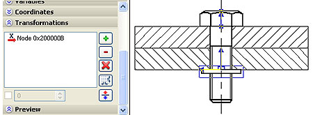
The washer "caught" the bolt's connector and requires additional shifting along the X-axis. The shifting is defined by a node
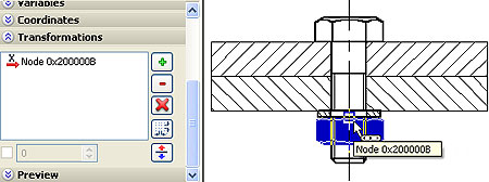
After snapping to the connector, additional shifting is defined for the nut along the X-axis
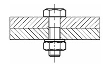
Completed bolt connection. Parameters were adjusted automatically due to connectors
New capabilities to control the mode of inserting a drawing as a fragment have been added in the Customize|Status� command's dialog in the [Fragment] tab. Now it is possible to define in advance in the fragment file, which status (of the assembly or of the fragment) will be used when inserting it. One can also specify there the main fixing vector of the fragment. The "Dynamic Fragment Editing" mode can be set in the [Preferences] tab which is used when creating and editing a fragment. Upon activating this mode, editing of variables or the fragment snaps automatically causes the redrawing of the elements related with the fragment. In this case, the image of the fragment being inserted is displayed with the same quality as the final result. The dynamic mode enhances the visual representation of the editing process. It can be useful when editing, for example, charts, plans, etc.
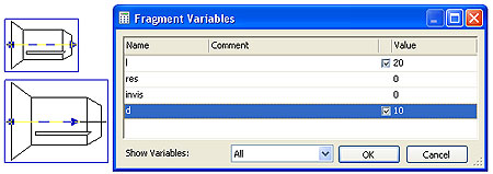
Fragment Variable Editor
Enhancements has been made to the fragment variable editor. The variables list is made customizable. The editor's customization settings are accessible by calling the "Settings" command via the context menu. The user can also manually impose or break the relation with the connector's value for the variables which are assigned the instruction to automatically snap to the connector. The relation is imposed with the flag which is set upon ![]() on the connector's icon in the fragment's variable editor.
on the connector's icon in the fragment's variable editor.
Editing Variables of Multiple Fragments
Whenever several fragments are selected simultaneously in the drawing, the "Variables" command called via the context menu allows to edit the variables of all selected fragments simultaneously. In this process, if differently named variables have different values, then the user can specify whether to modify the value of such a variable. To support this, an empty checkbox appears next to the value of such a variable, which needs to be switched on for editing.
Connectors
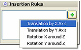
The properties window is now provided within the 2D connector creation command, which serves to define various parameters in the transparent mode. The user can define connector values, insertion rules applicable when the connector is in use, the list of associated elements which helps select the connector in the assembly drawing.
The capability to copy the list of connector variables to the clipboard and pasting new items from this list is added in the connector properties creation and editing commands. This allows to copy the list of variable values from one connector to another one.
Copying-Pasting Variables via the Clipboard
Two new commands are added in the context menu of fragments which allow to copy the variable values from one fragment to others. The "Copy to Clipboard" command copies the variable values and expressions into the internal clipboard. The "Paste from Clipboard" command replaces the values of the same-name variables of the selected fragments with the values put on the clipboard.
3D Fragments
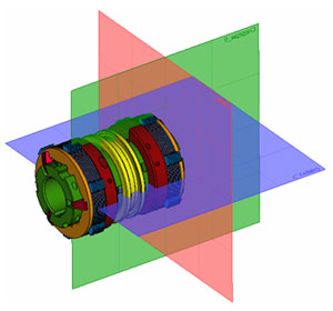
3D Connectors
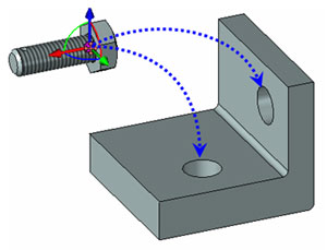
3D connectors are new model elements which serve to automatically relate external variables of the parametric elements of 3D assembly models which are being connected. This significantly simplifies positioning parts and matching parameters when designing assemblies. When a 3D fragment is being snapped to a 3D connector, the values of the connector's variables are automatically propagated to the fragment's model which is then recalculated. The fragment's preview from the beginning has the dimensions matching the connector variable values.
For example, suppose one needs to stack an M10 nut to an M10 bolt. At the time when the bolt was inserted into the assembly as the size ?10, its connector automatically remembered this diameter. Then, when the nut is inserted, the appropriate connector to snap the nut is automatically selected when we select the bolt's elements. The variable responsible for the nut's diameter has the instruction to query the variable value from the connector. If the names match, then the bolt's connector passes to the nut the value ?10. Therefore, right after selecting the connector, the parameters and the image of the nut are made consistent with the appropriate bolt.
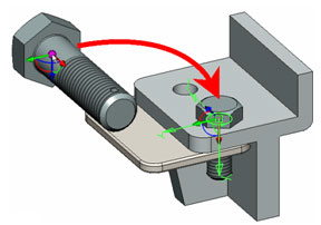
Clicking the connector (the edge) of the hole puts the bolt into the place and matches the diameter
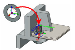
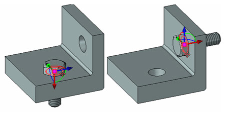
The bolt 's connector is selected, the washer moves upto the plate's face
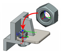
The bolt 's connector is selected, the nut moves upto the washer's face Thread parameters are matched automatically
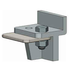
Completed bolt connectione
A 3D connector is created within the local coordinate system creation command. In fact, it is a local coordinate system which has the connector variable values defined and can be assigned associated elements. The associated elements simplify the connector's selection in the assembly: whenever such an element is selected at the time of inserting the 3D fragment (for example, a certain face or edge), the connector will be selected. A connector is displayed in the 3D scene in a special way.
 Connector |
 Regular LCS |
The insertion rules can be specified for a 3D connector which will be actual whenever this connector is selected in the assembly to snap a fragment. An insertion rule is an additional required definition of the fragment's position which is either its movement along one of the coordinate axes or its rotation about an axis (see the additional transformations of 3D fragments).
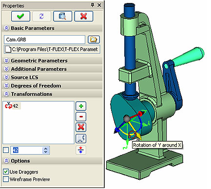
Additional Transformations of 3D Fragments
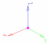
New 3D fragment parameters are introduced - "Additional Transformations". The types of the transformations are translation (movement) along the coordinate axes of the snapping coordinate system and rotation about those axes. The value of any additional transformations can be defined by either constants, variables or expressions, or by snapping to the model's geometrical objects.
The additional transformations are defined within the commands of 3D fragment insertion and editing. When defining transformations, one can use the draggers which appear as the axes of the fragment's target coordinate system. Additional transformations are added by selecting one of the dragger's axes and dragging the part in its direction. A rotation is added by selecting a dragger's arc.
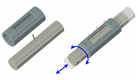
There are two modes of working with a dragger when fixing the position of the 3D fragment:
- the first way is selecting an element of the dragger by depressing and holding the left mouse button and thus dragging the part. When the mouse button is released, the part will be fixed in the space having the respective value of the additional transformation defined;
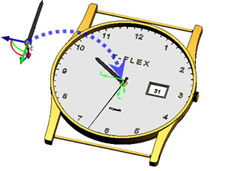 Begin with inserting a fragment (the minutes arm) by selecting the edge on the arm pin to define the target LCS (of the arm fragment position) |
 Turn the arm. To do this, select the desired element of the dragger and depress the left mouse button |
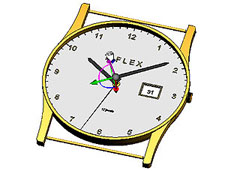 Drag the mouse whilst holding the mouse button down. Turn the fragment about the axis |
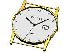 Complete the transformation definition by releasing the mouse button |
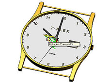
- the second way is to click the left mouse button and instantly release it when selecting the dragger, then the fragment's image will follow the mouse pointer. In this process, one can select model elements to snap to them. Another left mouse click will snap the fragment's image to the selected object or will fix it in the space.Note that whilst you define or edit additional transformations, the dragger's increment step size is customizable.
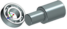 Start inserting the fragment (the bearing) |
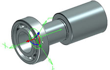 Select the round edge to define the target coordinate system (the fragment's position) |
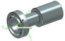 Click to select the dragger's axis to define the translation along the axis |
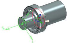 Select the round edge to define the final point of the translation |
Commands to Insert and Edit 3D Fragments
These commands have been significantly improved towards greater working comfort and speed:
- the capability is added to define fragment's additional transformations in the transparent mode. The additional transformation parameters can be defined using the properties window, by adding the desired translations and rotations with the relevant buttons. Also, upon clicking one of the dragger's axes or arcs, the system goes into the mode of defining additional transformations relative to the selected element of the dragger;
- whilst editing fragments one can toggle on/off the wireframe display mode. When the wireframe display is off, the fragment being inserted is displayed in the screen in its final appearance as upon confirming the creation;
- upon selecting the source coordinate system for the fragment's insertion, the fragment's position is now recalculated dynamically in the assembly model window;
- clicking any model element available for selection whilst editing the fragment means the action of changing the target coordinate system, and the fragment's image instantly takes the new position according to the parameters of the new target coordinate system;
- clicking the dragger's center whilst editing the 3D fragment initiates the change of the coordinate system. The fragment's image starts moving in the screen after the mouse pointer, with the dynamic snapping to model elements activated. A subsequent selection of a model element initiates the creation of a new target coordinate system. Clicking at an empty space results in the snapping with respect to the global coordinate system with additional transformations defined relative to the three axes;
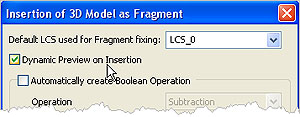
- in the fragment's file, in the Customize|Status command dialog, on the tab [3D], under the button [Fragment�] the parameter "Dynamic Preview on Insertion" may be preset.
|
|
In this case, the fragment, whilst is being inserted, goes into the dynamic object snapping mode right after the file selection. This mode enhances the visual comprehension of the insertion process. It is convenient when inserting 3D fragments which do not require much time for their display recalculation. This parameter is preset for the standard library items shipped with the system.
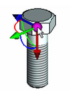
The dynamic snapping mode is active whenever library fragments are inserted
In the dynamic snapping mode, the fragment (a bolt) automatically assumes the desired position when the mouse pointer approaches the model element (the round edge of a hole)
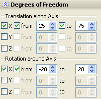
Restrictions on Degrees of Freedom of 3D Fragments
It is now possible to define the restrictions on various degrees of freedom in the properties of a 3D fragment. The restrictions are defined as a range limiting the translation or the rotation with respect to each of the fragment's target coordinate system axes. These restrictions are accounted for when transformations are being applied in the command Tools|Mates|Move Mated Components, as well as when performing the dynamic analysis studies.
Team Design with Fragments in Context of Assembly
Now several users simultaneously can access different parts of the same assembly when working with fragments in context of assembly (top-down design). All parts modifications will update in assembly at the moment of fragment saving. In the previous T-FLEX releases assembly file was locked by one of the users and concurrent design was impossible.Working with Drawings
2D Elements Marking
2D elements marking is realized with pure colors without "exclusive OR" (XOR) mode. This ensures better ergonomics and compliance with the latest Windows Vista operating system. Marking and selection are performed much faster especially for the big numbers of entities. This new method also eliminates the effect of disappearing elements on double selection. The marking color can be user customized for various types of elements.
Preview on elements creation in full compliance with their parameters
Preview for the elements being created displays them using all parameters including color. This preview fully corresponds to the final image of an element after input confirmation. This is true for image lines, detailing elements and 2D fragments.
Construction Lines
Construction lines command was perfected. Interface clearness when creating various tangent types of circles and lines was improved. Now, when selecting objects, it is possible to see the line being created as a preview. E.g., when user moves cursor to a circle, the line being created "jumps" to be tangent to this circle; if user selects a line and moves cursor to another line, then the preview line will become a bisector line.
New construction types were added:
- line tangent to ellipse and circle;
- line tangent to two ellipses;
- line tangent to ellipse and spline;
- line tangent to two splines;
- line parallel to another line and tangent to ellipse;
- line tangent to ellipse at angle to another line
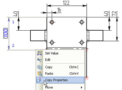
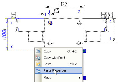
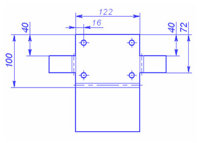
Commands to Copy-Paste Element Properties
The commands are added in the context menu of drawing elements that allow copying properties from one element to another one. The "Copy Properties" command copies the set of the selected element's properties into the internal clipboard. The "Paste Properties" command applies the set of properties from the internal clipboard to the selected elements.
Dimensions
New Dimension Types
The system allows to create new types of dimensions in drawings:
- the angular dimension by four points. This dimension type is now created automatically by the document import module. It is also helpful in certain cases of annotating a drawing. For example, it allows to create a dimension with 0 or 180� nominal value;
- the linear dimension by three points. This dimension type can be created manually. It is also used when importing a drawing;
- the leader dimension. It allows to create a dimension similar in the appearance to the "Leader Note" element. It is used in the export/import, as well as in the cases when, for instance, one needs to create a radius dimension where the circular arc is omitted due to a coarse detailing of the drawing.
 Angular by 4 points |
 Linear by 3 points |
 Leader dimension |
Commands to Create and Edit Dimensions
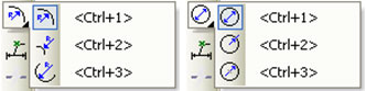
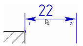
A number of improvements is made to dimension creation and editing commands to enhance the usability, in particular:
- the available snapping modes for radius and diameter dimensions are now arranged as drop-down lists in the automenu;
- the arrows of the dimension being edited are now marked with ordinal numbers for convenient parameters editing;
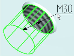
- provided is an extended set of options to calculate the nominal dimension value. a capability is added to introduce a correction;
- when creating a dimension in 3D, it is now possible to have the automatic display of thread parameters;
- 3D dimensions can now be oriented within the plane defined by the position of an arbitrary face or workplane.
|
|
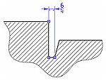
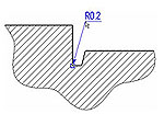
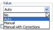
Editing Dimension Values
The dimension values editing function has been improved. If the user have set the "Manual" dimension value and defined a variable or an expression as a dimension value, then upon using the "Set value" command for this dimension, the system will automatically offer to modify the value of the relevant variable. This function is supported for both the 2D and 3D dimensions. This allows the user to relate dimensions with the appropriate variables and, if necessary, manually arrange for the parametric model management via dimensions.
New 3D Dimension Types
The 3D dimension creation command has been improved. It allows to create a large variety of new dimension types in 3D:
- between a plane and a point;
- between a plane and a straight edge;
- between a plane and the axis of a revolved surface;
- between straight edges;
- between an edge and a point;
- between points.
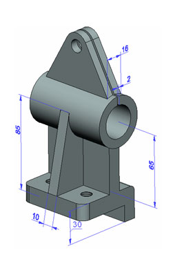
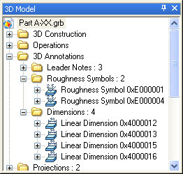
Drawing Annotation Elements
Placement of 3D Annotation Elements in the 3D Model Tree
The 3D model tree gained the folder "3D annotation elements". All annotation elements created on the 3D model elements are automatically placed in it. Those include dimensions, leader notes and roughness symbols.
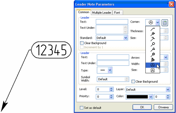
Custom Leader Notes
The mechanism of custom leader notes allows to use parametric fragments for the images being placed on the node leader. For this, one needs to save the fragment to the corresponding folder of the
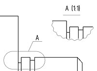
Drawing Views
The properties window is now provided within the drawing views creation and editing command, which serves to modify parameters in the transparent mode. The commands' work procedure has been simplified. When creating a detail view with caption, the system automatically selects the list of objects to copy to the drawing view in accordance with the shape and dimensions of the zone to be magnified. When creating a detail view, one can now use the new adjustable shapes for the magnification zone: "Freeform" and "Rectangle".
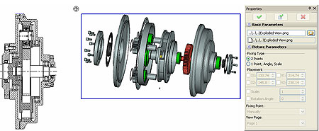
Pictures
Significant improvements have been made to picture insertion and editing commands. The commands now use the properties window for transparent editing of picture parameters. One can define the picture insertion option, its snapping coordinates, as well as select a
The capability is introduced to select a page to be inserted as a raster image file picture.
The new capability is introduced to create "internal" pictures maintaining the relation with the original file. This capability allows to capture in the picture the document image in the state it was at the time of the insertion.
For one of the colors of the bitmap pictures (e.g. background) it is possible to define transparency. This can be done with a new option in picture parameters - "Transparent Background". The color can be selected in the dialog box of parameters or directly by clicking the screen using the special option in automenu.
Text
The system gained the capability to control the stretch factor of TrueType fonts. It can now be other than the standard value of 1.
When numbering lists in paragraph text it is possible to set the string that will be added after the number:
![]()
2D Copy Commands
There is a new mode in all commands of creating 2D copies. It is called "Create Copy on Associated Construction". It allows to create associative copies of construction elements. Image elements created with this mode will be torn away from the source elements and will be attached to the newly created construction elements. These image elements can be edited if necessary. Note that for arrays created with this mode it is not possible to change the number of elements after creation. This new mode can be used in some drafting techniques that use copies of construction elements.
System Performance Enhancement
Faster 3D Model Display
Significant improvements are made in the system towards the comfort of working with large 3D models. Thanks to improvements in the internal data handling mechanism, large assembly documents are now drawn significantly faster. This is especially noticeable when working on computers with powerful graphics cards.
When working with very large assemblies, when the graphics card is lagging behind the required speed in redrawing the model, the assembly components become to be drawn as simplified boxes whilst being spun or zoomed. The desired spinning speed is defined in the Customize|Settings command's dialog on the [3D] tab, the button [Simplification�], as the number of frames per second. The system automatically makes the decision on the representation of a particular component being drawn depending on the component's dimensions and complexity. The simplified representation is first used for the components of small size and high complexity of the image.
Temporary image simplification to ease the model spinning in the 3D window
Normal image generated by a more powerful graphics card
Multithreading in recalculating 3D models
Improvements are made to T-FLEX CAD 11 which allowed to employ the multithreading mechanism for running the program on the computers with multicore processors or on multiprocessor systems. This resulted in a higher speed of recalculating models. The multithreaded data processing is used in calculating the geometry of 3D operations, in generating finite element meshes, in document converter operation.
Support for Accelerated Video and Windows Vista.
Serious improvements were done to support accelerated video cards and optimize support of Windows Vista operating system when working with 3D graphics.
General Changes
Spelling Check
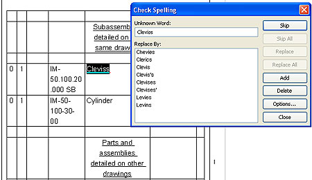
The text spellchecking commands allow to check the spelling of texts, whether within a drawing or just arbitrary texts inside edit boxes.
The spelling check of the text located in the drawing allows to visually review the spelling errors and with a mouse click go to the next word to be corrected.
The user has an opportunity to simultaneously check multiple texts on a page.
Text spellchecking within and edit box of a dialog is performed with the context menu command or with the function keys
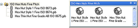
Libraries
The existing library "ANSY Inch Parts", "ISO Metric Parts", and "System" included in the installation has been improved. In line with the new functionality, the capability of using connectors is added for the items, and the dynamic snapping logic is fit which automatically activates for those items.
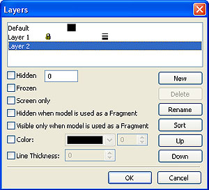
Layers management
The capability to alter the order of layers is introduced in the "Layers" dialog. This is managed with the buttons [Up] and [Down]. The order of the layers is accounted for in this dialog itself and in all the rest of the system dialogs which support the layer selection.
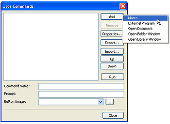
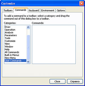
Custom commands
The new Customize| User Commands command is introduced which allows the user to create one's own commands. Such commands may include those for launching external applications, macros, opening a document, opening a folder window and opening a library window. Such a command may be assigned an icon (a .ico file). Any such command can further be put on any system bar or in the textual menu. For this purpose, the new "User Commands" group is introduced in the Customize|Customize� command in the [Commands] tab.
Variable Editor
One of the most important system tools - the variable editor has been significantly improved. A variety of new opportunities is introduced, and the working comfort is enhanced.
New Tool Window to Work with Variables
The new "Variables" window is added to the system's constantly active tool windows, which serves to work with variables in the transparent mode, simultaneously with working in the drawing field or with a 3D model. The new window is created in addition to the main variable editor window accessible via the command ![]() Parameters|Variables. Similar to other system's tool windows, the new window can be floating, popping, or it can be docked along one of the main system window's sides.
Parameters|Variables. Similar to other system's tool windows, the new window can be floating, popping, or it can be docked along one of the main system window's sides.
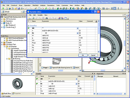
Upon changing a variable's expression in the "Variables" window, the drawing recalculates automatically. Any changes are immediately reflected in the drawing.
Should the user prefer to work with the variable editor in the traditional editor window, the original Parameters|Variables command will call it. It provides the fully functional textual menu and the toolbar.
New "Group" Variable Parameter
The T-FLEX CAD system variables gained the new "Group" parameter serving to group variables within the editor according to the user-defined rules.
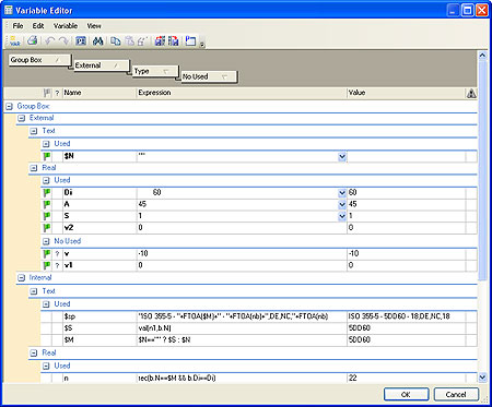
Customizing the Variable Editor
The variable editor gained the capability to customize various layout parameters to the user's preferences:
- sorting the variables order by any parameter;
- changing the order of columns by dragging their titles;
- showing or hiding columns as necessary. This can be done in the "Options" dialog of the editor or by using the context menu;
- grouping by any variable parameter. The grouping can be activated by using the context menu or by dragging a column's title to the special grouping area which in turn can be activated or deactivated;
- defining font parameters and the background color of the variables display;
- defining the line type of the editor table's grid.
Printing Capability
The variable editor gained the function to print the list of variables. Printing is performed per the current editor layout parameters settings.
Multiple Selection of Variables
The editor supports the selection of multiple variables using the keys
Copying-Pasting Variables
The variable editor gained the capability to use "Copy" and "Paste" commands to pass a list of selected variables from one document to another.
Stepwise Undo/Redo of Actions
The stepwise-action "Undo" and "Redo" commands became available in any of the variable editor's windows. The number of undo steps is limited by the general system setting.
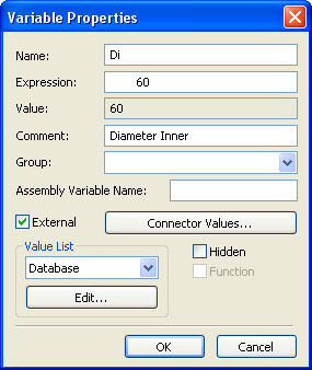
"Properties" Command for a Variable
When creating a variable or when using the new "Properties�" command for the selected variable, the dialog appears, in which you can modify most of the variable's properties, including its name. Some properties of a variable (value list and connector values) are defined in the separate additional dialogs called with the respective buttons: [Edit�] and [Connector values�]. Depending on the variable status, some variable properties dialog's controls may be inaccessible or missing.
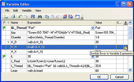
Error State Diagnostics
A significant improvements to the system's pattern of working with variables is the fact that now you can continue working with the model even if some syntax errors were left present in the variable editor. Should a variable's expression contain syntax errors, an exclamation mark glyph ![]() will appear in the "State" column, with a hint tool tip popping when pointed to with the mouse. In this case, the variable will maintain the old value, and the background of the "Value" field will change to red, signaling an error.
will appear in the "State" column, with a hint tool tip popping when pointed to with the mouse. In this case, the variable will maintain the old value, and the background of the "Value" field will change to red, signaling an error.
If desired, the user can activate the special "Message" column, which will display the entire error message. The user can finish working with the variable editor despite the presence of errors, and return to their correction later. The presence of errors in the variable editor no longer prevents the model's recalculation, where some of its elements are dependent on the erroneous variables, which provides a more flexible mechanism to correct problematic situations.
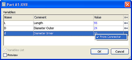
Capability to Define Names for Connector Values
To support the connectors mechanism which was improved in line with the concept of the new system version, the variables gained the new list of parameters. It appears in the editor's "Connector Values" column. The connector values can be defined in the variable's properties dialog or by double-clicking the appropriate column in the variable editor.The list of connector values for an external variable itemizes the names. A special check will be performed at the time of snapping a given fragment to the connector. If one of the names specified for this variable is found within the connector, then the external variable will read the appropriate value from the connector. The item coming earlier in the names list will be used first. For example, a bolt can be inserted either into a threaded or into a smooth hole, therefore several connector values shall be provided for the bolt's diameter, for the thread, and for the smooth hole. In this way, one can define the necessary conditions for a fragment's external variable in order for it to automatically read in the values when snapping this fragment to a connector of another fragment within an assembly.
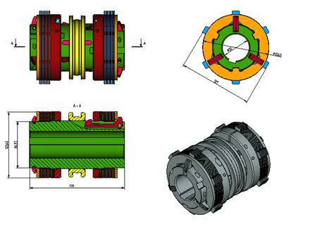
For example, suppose we are building the model of a bearing whose external parameter is the fitting diameter. Let the external variable "D" represent the bearing's diameter. In order to enable this variable to automatically assume a value, a connector value shall be registered for it. The name shall be the same as the one expected to be used in the connector of the shaft to which the bearing is to be fit, for example, this can be the value "Diameter". This is required in order to automatically match the variables of the shaft and the bearing, which may have different names but the same value (the fitting diameter).
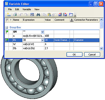
External variable D of the bearing is assigned "Diameter" value of the connector
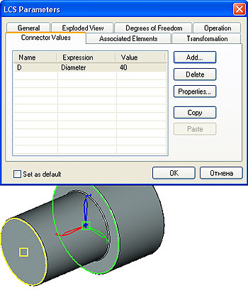
Shaft's connector is assigned "Diameter" value
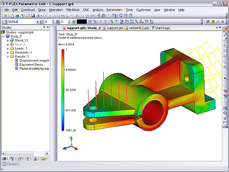
Express Analysis
The system's solver of the finite element analysis studies has been significantly improved. The improvements pertain to the enhanced performance and the reduction in the memory consumption for calculations. The solver and the finite element mesh generator can now run multiple threads, should the computer offer multiple processors or a multicore processor.
The set of buttons with the postprocessor commands automatically appears in the main bar whilst working in the postprocessor window.
Export/Import
The IGES 3D and STEP export and import algorithms have been improved. Importing models and assemblies from SolidWorks or from Solid Edge no longer requires the respective software license. New capability of importing Autodesk Inventor files is added, with the support for assemblies. AutoCAD 2008 is supported when working with the DWG/DXF graphics formats. There is now the Rhinoceros import and export capability.
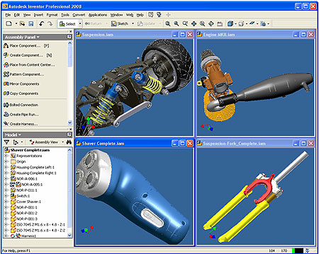
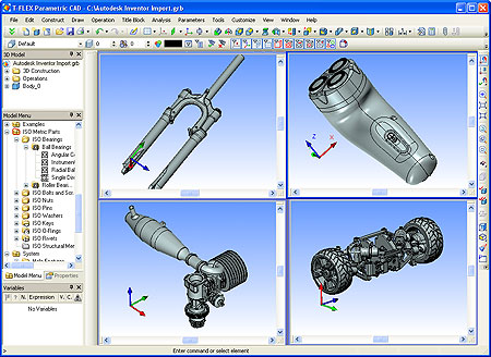
Autodesk Inventor 2008 imported model example
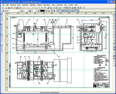
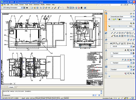
AutoCAD 2008 exported drawing example