T-FLEX CAD 17 - new tools for complex high-tech product high quality design, increased performance, improved interface and hundreds of user proposed innovations
T-FLEX CAD is a full-function software system providing mechanical design professionals with the tools they need for today's complex design challenges. It unites powerful 3D modeling functionality with the drafting and drawing production toolset.
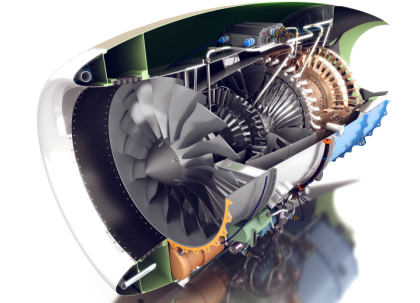
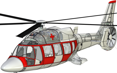
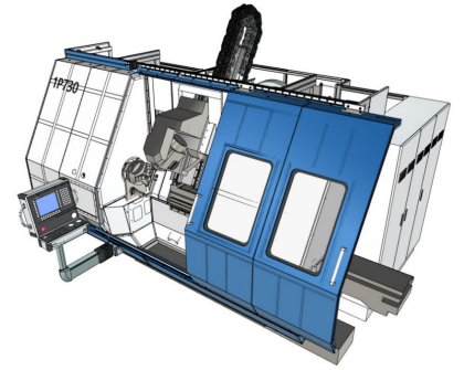
T-FLEX CAD is an industry leading mechanical design system with flexible and intuitive workflow and superior design capabilities. The technical innovations and productivity advantages have made T-FLEX one of the most robust and versatile modeling and drafting solutions for product development. Its extensive set of tools makes T-FLEX the best choice for meeting any professional challenge. T-FLEX is used extensively for everyday mechanical design applications including 3D/2D design, drafting, conceptual sketching, reverse engineering, tolerancing inspections, rapid prototyping, and downstream manufacturing.
Modeling Tools
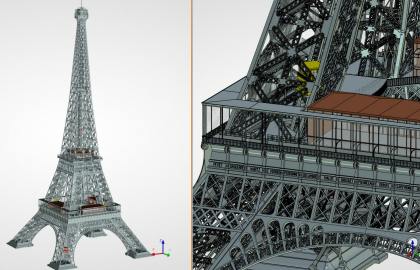
T-FLEX modeling and assembly tools enable your engineering team to easily develop a full range of products, from single parts to assemblies containing thousands of components. T-FLEX harnesses the power of Parasolid production-proven modeling kernel developed by Siemens Digital Industries Software Inc. Highly innovative modeling tools allow designers to quickly create basic shapes and easily add common mechanical features like holes, rounds and chamfers, as well as more complex geometry such as draft angles, lofts, sweeps, three-face blends, and helical features.
Design Workflow
T-FLEX supports a simple unified mode of operations for all types of documents and entities: drawings, assembly drawings, solids, surfaces, parts, parts with multiple solid bodies, assembly models, sheet metal, bill of materials, etc. You use a common set of editing and data management functions on all types of geometry, streamlining workflow.
Parametrics and Adaptivity
T-FLEX cuts down design steps by making changes that propagate instantly throughout your design, incorporating superior design engines for adaptivity ads. This functionality helps you for example associate parts in a way that allows the change of one part to drive changes in associated parts. Any thing in T-FLEX can be related to anything else. Variables can be assigned at any time for component names, visibility, material, any numeric or text attribute of any entity. They can then be processed with any algebraic or logical expression to control the behavior of the design. The variables themselves can be changed manually by dragging entities on the screen, typing values into the variable editor, or by reading ASCII or database files as assigned. Possibilities are endless and the interface is very intuitive. For this reason T-FLEX is a natural choice for family-of-parts manufacturers or any other design situations that use similar geometry but require many different sizes or permutations.
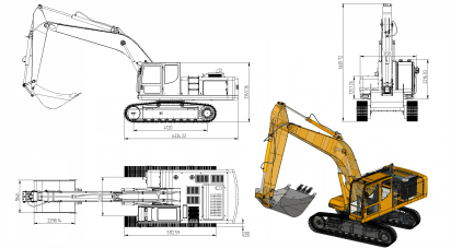
Parametric Drafting
Unlike other products, T-FLEX lets you create 2D drawings from scratch. The 2D CAD roots of T-FLEX are apparent when creating objects. When compared to most other solid modelers, even those focused on product design, T-FLEX has a much more robust palette of 2D tools, especially when it comes to drawing complex geometry. Its engine is the basis of T-FLEX design and unlike engines from other programs is not limited by the number of constrained 2D entities. T-FLEX drawing (parametric sketch for 3D operations) cannot be over or under defined. The drawing immediately updates to any changes regardless of their source. T-FLEX includes fully drawing documentation, including dimensions, tolerances, text, and drawing notes. You can create 2D assemblies by inserting 2D components with complex relations. The result can be fully automatic, so that a master drawing does not require any editing as changes are required. Constant re-documentation can be avoided through the use of the powerful documentations that are inherent in T-FLEX.
Creating Custom Dialog Boxes
Creating their own dialog boxes of model parameters directly inside T-FLEX users can control model in a very convenient and intuitive way. This unique functionality does not require any programming, programming knowledge or additional software installed.
T-FLEX is a Creative Tool
T-FLEX has one consistent characteristic for its history - its power is best utilized by the most creative designers. The interface is easy to learn and very consistent, but the real power lies in the incredible flexibility of design automation using functionality. From the beginning the goal was to provide engineers with access to creative design by giving them optimizing control over any aspect of the design process. The program's Total Flexibility approach can truly eliminate redundant tasks and enhance design efficiency.
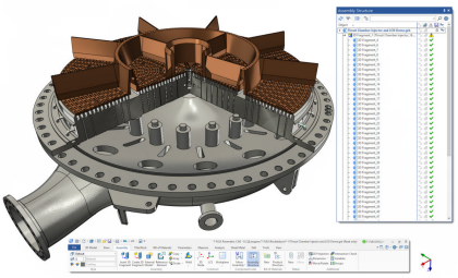
Assembly Modeling
T-FLEX easily tackles assembly 3D models that are fundamental to mechanical design. You can build complex assemblies consisting of many components using bottom-up design, top-down design, or a combination of both methods. Configuration management helps to simplify design reuse by creating multiple product variations within a single document. T-FLEX can simulate true motion and mechanical interaction between solids that allow you to avoid potential design flaws.
Adaptive Components
T-FLEX supports adaptive technology that allows creating assembly relationships by assigning geometrical links. With this you can capture design intent accurately, and manage and edit assemblies more easily.
Assembly Design Automation
Parametric connectors simplify assembly modeling by automatic parameter assignment for the parts being inserted. Parts location and sizes will adjust automatically on model modification. The structure of an assembly may be alterable. The drawings generated from a 3D assembly will update automatically on model modification with all detailing elements.
User-defined Features
The innovative technology of user-defined features substantially extends modeling functionality allowing users create their own modeling features. T-FLEX models may capture elements and geometry from other models as input parameters of operations inside their own model history tree. In that way any T-FLEX model can be defined as a special feature that will function equally with other modeling commands. This mechanism can dramatically reduce the modeling time providing users with the possibility of creating their own features and libraries of features for specific modeling tasks.
Deformation Commands
The set of deformation commands provide a simple way to change shapes of complex surface or solid models. Deformation may be applied either in a local area or globally. Various options may be specified by direct rules and parameters or via the special handlers. Fast preview based on input data is available prior to exact model generation.
Surfacing
T-FLEX synergistically combines solid and surface modeling enabling designers to extrude, sweep, revolve, and loft surfaces as can be done with solid models. It also enables to do things that can't be done with solids alone. For example, a designer can draw lines or curves in space and fit surfaces between them, or add surfaces that blend between non-intersecting surfaces. Integrated surface and solid modeling provides flexibility in making design changes through the use of constraints and associative operations.
Direct Editing
T-FLEX supports direct editing of 3D models, retaining history of the edits so that they can be regenerated. This is very helpful for the imported models when there is no access to the original history tree. For example it is possible to modify parameters of the faces whose underlying surfaces are analytical (cylinder, cone, sphere and torus), as well as the parameters of faces created as blends. Other editing features include imprinting, face replacement, face extension, face removing, body separation, etc.
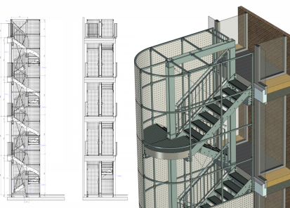
Detailing Features
Professional detailing functions support quick creation and complete manipulation of all common annotations used on mechanical drawings. T-FLEX contains an unmatched set of capabilities for the 2D documentation process, with excellent drawing layout, detailing, annotation and dimensioning controls that automatically comply with the mechanical drafting standard you select. Streamlined drawing creation T-FLEX automatically creates and updates drawings from 3D models, quickly creating standard and auxiliary views, including section, detail, broken and isometric views. T-FLEX provides flexibility and control of section views with improved control of the depth of a slice and selection tools that allow you to predefine components on a per view basis when creating section views. As changes are made to parts or assemblies, associated drawings update automatically. With T-FLEX, you have full control over every element of your drawings, so you know that they meet the requirements of organizational and international standards. Additional advanced capabilities, such as threaded connections, intelligent hatching of assembly sections, and accurate local sections, can significantly increase detailing productivity. T-FLEX's associative detailing tools help avoid costly errors by preventing incorrect annotations from reaching production drawings.
Associative Bill of Materials (BOM)
T-FLEX can generate and update an accurate BOM in a fraction of the time required by traditional 2D methods. Part and subassembly quantities are always kept up to date, and are instantly organized and populated into a drawing BOM. Changes to the assembly (removing a part, for example) are associative, so the BOM table is updated automatically. BOM templates and table properties (column headings, sorting, title blocks, etc.) are fully customizable.
Integrated Sheet Metal Design
T-FLEX provides a set of commands tailored for the efficient construction of sheet metal parts from design of sheet metal components to flat pattern development and the creation of engineering drawings.
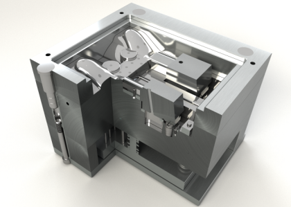
Mold Design
T-FLEX provides a sequence of integrated tools that control the mold creation process. You can apply body taper; generate parting lines and surfaces; resize the model's geometry to account for the shrink factor when plastic cools; perform tooling split to separate core and cavity. With the model finished, you can examine it for potential problems that might prevent the core and cavity from separating.
Express FEA
Built-in Express Analysis offers an easy-to-use first pass stress analysis tool that enables design engineers to execute design verification directly in T-FLEX CAD. It helps to determine how designs will perform under real-world conditions, and identify potential design flaws before expensive physical prototypes are built. Express Analysis uses the same design analysis technology that professional FEA add-on module uses to perform stress analysis. More advanced analysis capabilities are available within the T-FLEX Analysis line of products.
Interactive Motion Simulation
T-FLEX provides a motion simulation solution for analyzing the complex behavior of mechanical assemblies. T-FLEX Dynamics allows you to test virtual prototypes and optimize designs for performance, safety, and comfort, without having to build and test numerous physical prototypes. Results are viewable as graph, data plots, reports, or colorful animations that you easily can share with others.
Weldment Design and Documentation
T-FLEX lets you work in a weld-specific environment with functionality tailored to the unique design requirements of designing and documenting weldments. Model weldment annotations are associated with the model and automatically get updated when the model is changed.
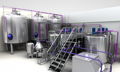
Piping and Cabling Design
T-FLEX CAD includes design tools that automate routed systems design. It speeds up the process of routing tube, pipe, venting, electrical cable, and harnesses across various manufacturing industries and types of piping and cabling systems.
Open API
T-FLEX Open API is based on .NET technology offering customers and third-party developers extensive possibilities for developing add-on applications in various areas. T-FLEX's set of entities can be extended with the custom objects. T-FLEX Open API supports full object oriented programming concepts and multiple programming languages with identical functional access to all T-FLEX functionality. It also helps users to customize T-FLEX for their specific environment and automate specialized workflows.
Product Manufacturing Information (PMI)
T-FLEX delivers the functionality needed to produce 3D-annotated designs to serve as single digital representations capturing all product information, reducing or eliminating the need for drawings in design reviews or manufacturing. Support for PMI technology allows the user to take established drawing dimensioning and annotation methods and take them to the 3D realm. It helps to generate a 2D drawing, extracting much of the vital detailing information automatically. It is also possible to modify a 3D model directly by changing the values of the 3D dimensions.
Parametric Engine for Internet
Using T-FLEX and T-FLEX Open API, third parties, OEMs, developers, and system integrators can deliver CAD functionality across a wide range of Internet-based products. T-FLEX utilized as an Internet engine, provides engineers, manufacturers and distributors with opportunity to display their products, use third-party designs and perform marketing activities.
Multilingual Support
T-FLEX is a Unicode application and hence supports all of the languages around the world. Unicode support in T-FLEX means that users can utilize multilingual text that will be displayed correctly in T-FLEX documents. There will be no problems with any language files names under any language version of Windows operating system. Users can name objects and parameters in whatever language they like.
Interface Flexibility
T-FLEX's multiple interface options help maximize productivity by allowing users to choose an interface that matches their experience and preferences. The user interface is specifically designed to remove command clutter and operational complexity. The Windows-style pull-down menu interface is easy to navigate. Compact text-based command bar, icon toolbars and shortcut key assignments are also available. Enhanced capabilities, such as intelligent posi7tioning tools and pop-up menus driven by hotkey activation, greatly simplify workflow. T-FLEX provides direct model interaction, using 3rd mouse button, dynamic geometry preview, and support for SpaceMouse� to seamlessly blend frequent and advanced capabilities.
Advanced Graphics Subsystem
High performance 3D graphics mechanisms ensure convenient operations even with very large assemblies. There is also the possibility to generate high-quality photorealistic images based on lighting and material properties such as transparency, refractive index, surface properties, etc.
Translators
The rich suite of T-FLEX translators enables you to satisfy differing import and export requirements, effortlessly. T-FLEX is interoperable with the most widely used 3D-modeling and 2D-drawing systems via the following formats: Siemens NX, CATIA, Creo (Pro/E), Autodesk Inventor, Solid Edge, SolidWorks, Parasolid, ACIS, JT, IGES, STEP, Rhino, Revit, IFC, STL, DWG, DXF, PDF/3DPDF etc. Additionally, T-FLEX provides options for exporting graphical images to presentations, web pages, and other documentation.
3D Printing
With T-FLEX CAD you can print your models to 3D printers via STL, a widely accepted format, as well as other output formats (3MF, OBJ, PLY, etc.). In addition to the model geometry, output file can contain information about the color of objects. You may customize the quality of the result using various parameters.
 Unlike other products,
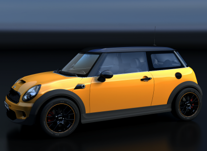
 Parametric connectors simplify assembly modeling by automatic parameter assignment for the parts being inserted. Parts location and sizes will adjust automatically on model modification. The structure of an assembly may be alterable. The drawings generated from a 3D assembly will update automatically on model modification with all detailing elements.
 Professional detailing functions support quick creation and complete manipulation of all common annotations used on mechanical drawings.
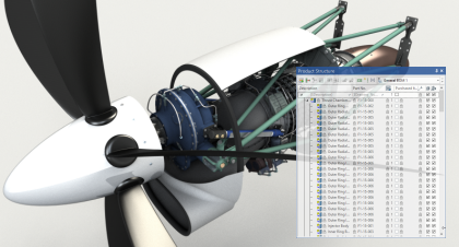
 T-FLEX lets you work in a weld-specific environment with functionality tailored to the unique design requirements of designing and documenting weldments. Model weldment annotations are associated with the model and automatically get updated when the model is changed.